
Installation Manual

Page 32
© 2010 Magnum Energy, Inc.
Installation
This electrical system is equipped with an Automatic
Generator Starting (AGS) device and/or an inverter.
Disconnect all AC and DC power to the AGS and/or
inverter before performing any service to the electrical
system. Failure to do so can result in shock causing
serio us i njury or de ath .
PN: 62-0002 Rev A
2.8 Final Inspection
Verify all cables/conduit runs are secured with wire ties or other non-conductive fasteners to
prevent chafi ng, or damage from movement and vibration.
Verify strain reliefs or grommets are in place to prevent damage to the wiring or conduit where
it passes through walls or other openings.
Verify all AC connections are correct and torqued to a maximum of 16 in lbf (1.8 N-m).
Replace the covers on the main electrical/distribution panel.
Replace the chassis access cover.
Verify the inverter’s front panel switch is in the OFF position.
Info: If required by code, have the installation inspected by an electrical inspector.
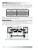
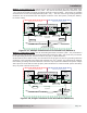
2.9 Functional Test
After all electrical connections to the inverter, batteries, AC source, and sub-panel have been
completed, follow these steps to test the installation and the inverter operation.
CAUTION: Use a multimeter to verify the correct DC voltage for your particular inverter
model (i.e., 24-volt battery bank for a 24-volt inverter), and to ensure the polarity of the
battery voltage is correct (battery positive connected to inverter positive, and battery
negative connected to inverter negative).
1. Apply battery power to the inverter by closing the DC circuit breaker or inserting a fuse. The
inverter will remain OFF, but the green status indicator on the front of the inverter will quickly
blink once to indicate that DC power has been connected and is ready to be turned on.
2. Prior to turning on the inverter, make sure all AC loads (e.g., appliances) are NOT connected
to the inverter’s output or to any AC outlets powered by the inverter.
3. Lightly press and release the inverter’s ON/OFF switch to turn the inverter ON. Verify the
inverter’s status indicator is blinking – indicating the inverter is ON.
4. Connect a small light bulb no larger than 75 watts to the inverter output and verify it comes on
and shines normally. DO NOT connect anything but a light bulb until all wiring and voltages are
confi rmed to be correct.
1.
2.
3.
4.
5.
6.
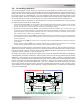
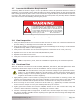
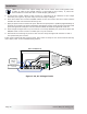
2.7 Inverter Notifi cation Requirements
A warning label as shown in Figure 2-19 is provided to inform all personnel that an inverter is
installed in your electrical system. Affi x this label in a clearly visible location by the electrical panel
that is being powered by the inverter. This is because it might be falsely assumed that the panel is
no longer “hot” after the AC power has been shut off, when power may actually still be available
due to the inverter automatically powering the panel.
Figure 2-19, Warning Label
This electrical system is equipped with an Automatic
Generator Starting (AGS) device and/or an inverter.
Disconnect all AC and DC power to the AGS and /or
inverter before performing any service to the electrical
system. Failure to do so can result in shock causing
serious injury or death . PN: 62-0002 Rev A