
Installation Manual

© 2010 Magnum Energy, IncPage 7
Installation
2.0 Installation
WARNING: Installations should be performed by qualifi ed personnel, such as a licensed
or certifi ed electrician. It is the installer’s responsibility to determine which safety
codes apply and to ensure that all applicable installation requirements are followed.
Applicable installation codes vary depending on the specifi c location and application of
the installation.
CAUTION: Review the “Important Product Safety Information” on page ii, and the
“Important Battery Safety Instructions” on page iii before any installation.
CAUTION: The inverter is heavy. Use proper lifting techniques during installation to
prevent personal injury.
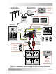
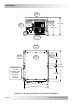
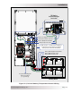
The simplifi ed system diagram shown in Figure 2-1 should be reviewed to assist you in planning
and designing your installation. This drawing is not intended to override or restrict any national
or local electrical codes. This drawing should not be the determining factor as to whether the
installation is compliant, that is the responsibility of the electrician and the onsite inspector.
2.1 Pre-Installation
Before installing the inverter, read the entire installation section to determine how you are going
to install your RD inverter/charger. The more thorough you plan in the beginning, the better your
inverter needs will be met.
2.1.1 Unpacking and Inspection
Carefully remove the RD Series inverter/charger from its shipping container and inspect all contents.
Verify the following items are included:
The RD Inverter/Charger
Red and black DC terminal covers with Phillips screws
AC access cover with two Phillips screws
Two 5/16” Kep or Flange nuts (installed on the DC terminals)
Battery Temperature Sensor
Warning label
RD Series Owner’s Manual
If items appear to be missing or damaged, contact your authorized Magnum Energy dealer or
Magnum Energy. If at all possible, keep your shipping box. It will help protect your inverter from
damage if it ever needs to be returned for service. Save your proof-of-purchase as a record of
your ownership; it will also be needed if the unit should require in-warranty service.
Record the unit’s model and serial number in the front of this manual in case you need to provide
this information in the future. It is much easier to record this information now, instead of trying
to gather it after the unit has been installed.
2.1.2 Required Tools and Materials
Hardware/Materials
Conduit, strain-reliefs, and appropriate fi ttings• 1/4” mounting bolts and lock washers•
Electrical tape• Wire ties•
Tools
Miscellaneous screwdrivers• Pliers• Wire strippers•
Drill and drill bits• Pencil or marker• Multimeter•
Level• 1/2” wrench•
•
•
•
•
•
•
•