
Installation Manual

© 2010 Magnum Energy, IncPage 9
Installation
2.1.3 Locating the Inverter
Only install the inverter in a location that meets the following requirements:
Clean and Dry - The inverter should not be installed in an area that allows dust, fumes, insects, or
rodents to enter or block the inverter’s ventilation openings. This area also must be free from any
risk of condensation, water, or any other liquid that can enter or fall on the inverter. The inverter
uses stainless steel fasteners, plated copper busbars, and a power-coated aluminum base. The
internal circuit boards are conformal coated. All of this is done to help fi ght the harmful effects
of corrosive environments. However, the inverter’s life is uncertain if used in the above types of
environments, and inverter failure under these conditions is not covered under warranty.
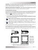
Info: If the inverter is installed in an area where moisture may occur, we
recommend putting silicone dielectric grease compound into the electrical ports
(see Figure 1-1, Items 3-6). Before installing the cables, or if leaving any ports open,
squirt a liberal amount into each port. Silicone dielectric makes an effective moisture
and corrosive barrier to help protect and prevent corrosion to the RJ11 connections.
Cool - The inverter should be protected from direct sun exposure or equipment that produces
extreme heat. The ambient temperature around the inverter must not exceed 77°F (25°C) to
meet power specifi cations.
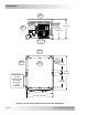
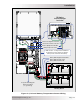
Ventilation - In order for the inverter to provide full output power and avoid over-temperature
fault conditions; do not cover or block the inverter’s ventilation openings, or install this inverter in
an area with limited airfl ow. The inverter uses two fans to provide forced-air cooling. These fans
pull in air through the intake vents (see Figure 1-2, Item 9) and blow out air through the exhaust
vents (see Figure 1-3, Item 13). Allow at the minimum an airspace clearance of 6” (15.2 cm) at
the intake and exhaust vents, and 3” (7.6 cm) everywhere else to provide adequate ventilation.
If installed in an enclosure, a fresh-air intake opening must be provided directly to the front side
(intake vents) of the inverter, and an exhaust opening on the back side (exhaust vents) of the
inverter. This allows cool air from the outside to fl ow into the inverter, and heated air to exit the
inverter and the enclosure. When mounted in an enclosed compartment, airfl ow must be ≥ 100
cfm in order to maintain no more than a 68°F (20°C) rise in compartment temperature.
CAUTION: Do not mount this inverter in a zero clearance compartment, nor cover or
obstruct the ventilation openings – overheating may result.
Safe - Keep any fl ammable/combustible material (e.g., paper, cloth, plastic, etc.) that may be
ignited by heat, sparks, or fl ames at a minimum distance of 2 feet (61 cm) away from the inverter.
Do not install this inverter in any area that contains extremely fl ammable liquids like gasoline or
propane, or in locations that require ignition-protected devices.
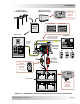
Close to the battery bank - As with any inverter, it should be located as close to the batteries as
possible. Long DC wires tend to loose effi ciency and reduce the overall performance of an inverter.
However, the unit should NOT be installed in the same compartment as the batteries, or mounted
where it will be exposed to gases produced by the batteries. These gases are corrosive and will
damage the inverter; also, if these gases are not ventilated and allowed to collect, they could ignite
and cause an explosion.
Info: The battery bank should be installed in a clean, dry, ventilated environment where
they are protected from high and low temperatures. The batteries must be mounted
upright (if using liquid batteries) and securely fastened. The location must be fully
accessible and protected from exposure to heat producing devices, and away from any
fuel tanks.