
Installation Manual


Page 30
© 2010 Magnum Energy, Inc.
Installation
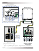
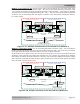
Method 2 (see Figure 2-17): When the AC and DC service panels are near each other, then
the AC Grounding Electrode Conductor (GEC – AC) and DC Grounding Electrode Conductor (GEC
– DC) can be connected to a single grounding electrode. In this method — since there are multiple
connections to the DC Grounding Electrode (GEC – DC) — the size of the DC grounding electrode
conductor can not be smaller than the largest conductor in the DC system (usually the battery-
to-inverter cable).
AC
DC Service
Panel
AC Service
Panel
DC Electrical SystemAC Electrical System
Neutral
Positive
Negative
DC
Grounding
System
Negative
SBJ
GC
GE
GEC-AC
EGC - AC
AC Ground DC Ground
SBJ
EGC - DC
GC
Neutral
Hot
GEC-DC
GBB GBB
Grounding Electrode
(AC and DC sides shared)
RD Series Inverter/Charger
Figure 2-17, Multiple Connections to DC Ground Rod (Method 2)
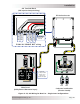
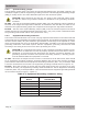
Method 3 (see Figure 2-18): The AC Grounding Electrode Conductor (GEC – AC) is bonded to
the DC ground point and the DC Grounding Electrode Conductor (GEC – DC) is the only connection
to the grounding electrode, which must be a rod, pipe, or plate electrode.
In this method, since there is only one connection to the ground rod, the DC grounding electrode
conductor is not required to be larger than #6 AWG (13 mm
2
) copper. The reasoning for allowing
this smaller grounding electrode conductor is that it is only required to stabilize the system voltage
with respect to earth and the other properly sized conductors in each electrical system will safely
carry any fault currents if they occur.
AC
DC Service
Panel
AC Service
Panel
DC Electrical SystemAC Electrical System
Neutral
Positive
Negative
DC
Grounding
System
Negative
SBJ
GC
GEC-AC
EGC - AC
AC Ground DC Ground
SBJ
EGC - DC
GC
Neutral
Hot
GEC-DC
GE
GBB GBB
Grounding Electrode
(DC side dedicated)
RD Series Inverter/Charger
Figure 2-18, Single Connection to DC Ground Rod (Method 3)