-1- Magnum Dynalab MD 309 HYBRID INTEGRATED AMPLIFIER INSTRUCTION MANUAL
-2- TABLE OF CONTENTS DEAR VALUED CUSTOMER .............................................................................................. 3 UNPACKING YOUR MD 309 HYBRID INTEGRATED AMPLIFIER ................................... 4 SETTING UP THE MD 309 HYBRID INTEGRATED AMPLIFIER ...................................... 5 INPUT PRESET VOLUME PROCEDURE .....................................................................................................................
-3- Dear Valued Customer Thank you for choosing the Magnum Dynalab MD 309 Hybrid Integrated Amplifier. Great care has been given to the design, manufacturing and selection of components for the MD 309 Hybrid Integrated Amplifier. This complete process insures optimum listening enjoyment for many years. When using these high grade components, a considerable length of time is required for the MD 309 Hybrid Integrated Amplifier to reach its full potential.
-4- UNPACKING YOUR MD 309 HYBRID INTEGRATED AMPLIFIER Carefully inspect all sides of the shipping carton for damage. If there are marks or holes in the carton make note of the location in relation to the unit inside. Any obvious dents or scuff marks should alert you to the possibility of damage. Carefully remove the MD 309 Hybrid Integrated Amplifier from the end caps and wrapping, inspect all sides. Pay special attention to the corresponding areas on the unit where damage was found to the shipping carton.
-5- SETTING UP THE MD 309 HYBRID INTEGRATED AMPLIFIER 1. Position the unit away from any spot which may have extremes in temperatures. 2. Place the unit on a very rigid surface capable of holding 50 pounds (22 KG). 3. The heat sinks located inside the unit are used to keep the unit at a safe operating temperature. It is important that they are not covered and that the unit is not installed in a closed area where there is little air circulation.
-6-
-7- CONNECTING ADDITIONAL SOURCES TO THE MD 309 HYBRID INTEGRATED AMPLIFIER CAUTION As standard practice, you should always turn off the main power to the MD 309 Hybrid Integrated Amplifier (found on the rear panel of the unit) whenever any source component, interconnect or loudspeaker is being changed in your system. 1. Using your RCA cables, balanced XLR cables, coaxial, or USB, plug the source(s) into one of the inputs marked in the back of the MD 309. 2.
-87. Hit the button marked “SSP” and then “Save”. 8. When the screen goes back to the main screen it should now read SSP and the volume control will have no effect on the level. HOOKING UP A SUBWOOFER TO YOUR SYSTEM 1. Unplug the power cord to the MD 309 Hybrid Integrated Amplifier. 2. Using RCA cables, connect one end to the Pre Out output marked on the rear of the 309, the other end to your subwoofer. 3. Turn the subwoofer “ON”. 4. Re-connect the power to the MD 309 Hybrid Integrated Amplifier.
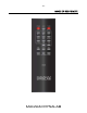
-9- RC6 REMOTE CONTROL Unpacking the Remote: • Remove the remote from its plastic bag, and install the 2 “AA” batteries provided • Test the remote to make sure that all functions are operating correctly. FUNCTIONS OF THE RC6 REMOTE 1. POWER MAIN: Power ON & OFF 2. VOLUME UP/VOLUME DOWN: Increase or reduces the volume level of the preamplifier section of the MD309 Hybrid Integrated Amplifier. 3.
- 10 - IMAGE OF RC6 REMOTE
- 11 - CONTROL/DISPLAY FUNCTIONS (Numbers correspond with product diagram on page 11) 1. INPUT SELECTOR – Changes the input source sequentially. 2. LEFT CHANNEL METER – Indicates the volume level of the left channel in dB. 3. TOUCHSCREEN DISPLAY/POWER – The main display for the MD 309 Hybrid Integrated Amplifier. This is used to power up the unit, adjust the volume, and display the input and volume level. 4. RIGHT CHANNEL METER – Indicates the volume level of the right channel in dB. 5.
- 12 - DIAGRAM OF MD 309 HYBRID INTEGRATED AMPLIFIER
- 13 - TROUBLE SHOOTING PROBLEM No sound, meter lights are not on POSSIBLE CAUSE • Power cord disconnected • Power off at source • Fuse blown • Interconnect not properly installed • Preamp set to wrong source • Power amp off POSSIBLE SOLUTION • Connect power cord • Check AC source • Check rear panel fuse • Check installation of interconnects • Turn preamp to other input • Turn on amp
- 14 - SPECIFICATIONS Power Output Audio Frequency Response (+/-0.1dB) Signal to Noise Ratio Total Harmonic Distortion Class of Operation Input Impedance Output Impedance after volume control Inputs Outputs Output Sensitivity Fully Balanced Amplifier Design Safety Diagnostic System Dynamic Headroom Dimensions (W.D.H.) Shipping Weight Fuse Replacement Tube Specifications Warranty (Tubes/Touchscreen) 225 Watts into 8 Ohms, 450 Watts into 4 Ohms + Zero, -0.25dB, 2Hz - 100KHz -110dB, A Weighted 0.
- 15 - SAFETY SHEET IMPORTANT SAFETY INSTRUCTIONS 1. 2. 3. 4. 5. 6. KEEP THESE INSTRUCTIONS HEED ALL WARNINGS FOLLOW ALL INSTRUCTIONS DO NOT USE THIS APPARATUS IN WATER CLEAN ONLY WITH DRY CLOTH DO NOT BLOCK ANY VENTILATION OPENINGS, INSTALL IN ACCORDANCE WITH THE MANUFACTURER’S INSTRUCTIONS. 7. DO NOT INSTALL NEAR ANY HEAT SOURCES SUCH AS RADIATORS, HEAT REGISTERS, STOVES, OR OTHER APPARATUS (INCLUDING AMPLIFIERS) THAT PRODUCE HEAT. 8. DO NOT DEFEAT THE SAFETY PURPOSE OF THE GROUNDING TYPE PLUG.
- 16 - LIMITED WARRANTY Register your product at www.magnumdynalab.com Magnum Dynalab Ltd. herein referred to as the “manufacturer” guarantees this product to be free of defect in both material and workmanship and agrees to remedy any such defect or replace any defective component at no charge for a period of two years from date of sale to the first end user.
- 17 TO PREVENT FIRE SHOCK OR HAZARD, DO NOT EXPOSE THIS APPLIANCE TO RAIN OR MOISTURE. TO REDUCE THE RISK OF ELECTRIC SHOCK, DO NOT REMOVE COVER OR FACEPLATE, NO USER SERVICEABLE PARTS INSIDE. REFER SERVICING TO QUALIFIED SERVICE PERSONNEL.