DIESEL GENERATOR MMG75 • MMG100 ww w m -p -ll c co m 10 0 OPERATING MANUAL
INTRODUCTION This manual provides information and procedures to safely operate and maintain the engine and generator. For your own safety and protection from physical injury, carefully read, understand, and observe the safety instructions described in this manual. The information contained in this manual was based on machines in production at the time of publication. Magnum Products LLC reserves the right to change any portion of this information without notice.
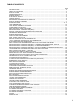
TABLE OF CONTENTS Page INTRODUCTION ............................................................................................................................... 2 TABLE OF CONTENTS ..................................................................................................................... 3 SAFETY NOTES ............................................................................................................................... 4 OPERATING SAFETY ................................................
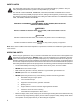
SAFETY NOTES This is the safety alert symbol. It is used to alert you to potential personal injury hazards. Obey all safety messages that follow this symbol to avoid possible injury or death. This manual contains DANGERS, WARNINGS, CAUTIONS, NOTICES and NOTES which must be followed to prevent the possibility of improper service, damage to the equipment, personal injury or death.
ENGINE SAFETY Internal combustion engines present special hazards during operation and fueling! Failure to follow the safety guidelines described below could result in severe injury or death. Read and follow all safety warnings described in the engine operator's manual. A copy of this manual was supplied with unit when it was shipped from the factory. • DO NOT run engine indoors or in an area with poor ventilation.
TOWING SAFETY Towing a trailer requires care! Both the trailer and vehicle must be in good condition and securely fastened to each other to reduce the possibility of an accident. Also, some states require that large trailers be registered and licensed. Contact your local Department of Transportation office to check on license requirements for your particular unit.
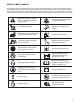
SAFETY SYMBOL SUMMARY This equipment has been supplied with numerous safety and operating decals. These decals provide important operating instructions and warn of dangers and hazards. Replace any missing or hard-to-read decals and use care when washing or cleaning the unit. Decal placement and part numbers can be found in the parts section or parts manual included with your unit. Below is a summary of the intended meanings for the symbols used on the decals.
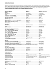
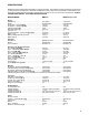
SPECIFICATIONS Read this manual carefully before attempting to use this generator. The potential for property damage, personal injury or death exists if this equipment is misused or installed incorrectly. Read all of the manuals included with this unit. Each manual details specific information regarding items such as set up, use and service requirements. SPECIFICATIONS ARE SUBJECT TO CHANGE WITHOUT NOTICE. MAGNUM MODEL MMG75 MMG75 Super Start Engine Make/Brand.............................................
SPECIFICATIONS Read this manual carefully before attempting to use this generator. The potential for property damage, personal injury or death exists if this equipment is misused or installed incorrectly. Read all of the manuals included with this unit. Each manual details specific information regarding items such as set up, use and service requirements. SPECIFICATIONS ARE SUBJECT TO CHANGE WITHOUT NOTICE. MAGNUM MODEL MMG100 MMG100 Super Start Engine Make/Brand...........................................
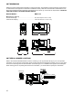
UNIT DIMENSIONS Read this manual carefully before attempting to use this generator. The potential for property damage, personal injury or death exists if this equipment is misused or installed incorrectly. Read all of the manuals included with this unit. Each manual details specific information regarding items such as set up, use and service requirements. SPECIFICATIONS ARE SUBJECT TO CHANGE WITHOUT NOTICE. MAGNUM MODELS MMG75/100 Dimensions (L x W x H) Skid Mounted in (m) ................................
COMPONENT LOCATIONS RADIATOR ACCESS PANEL CENTRAL LIFTING EYE 100 VOLTAGE SELECTOR SWITCH ACCESS FUEL FILL ENGINE ACCESS LEFT SIDE ENGINE EXHAUST EMERGENCY STOP ENGINE ACCESS 100 ENGINE BATTERY ACCESS CONTROL PANEL ACCESS RADIATOR DRAIN PORT RIGHT SIDE OIL DRAIN PORT 11
MAIN CONTROL PANEL FEATURES 5 6 7 MAN AUT 4 Ready PF RPM 0 k 0.
1. GENERATOR GROUND CONNECTION LUG: This lug is for connecting a good earthen ground per any local, state or National Electric Code (NEC) guidelines before starting the generator. 2. GENERATOR OUTPUT CONNECTION LUGS: These lugs allow appropriate loads to be wired directly to the generator. 3. CONNECTION FOR BATTERY CHARGER (OPTIONAL): This outlet allows for 120VAC input to power onboard battery charger. 4. MAIN CIRCUIT BREAKER: This breaker will disconnect power to the connection lugs (items 1-2).
MAGNUM DIGITAL CONTROLLER (MDC) The Magnum Digital Controller (MDC) is an enhanced digital generator controller used to start, stop and monitor the operation of the generator and the engine. The controller constantly monitors vital generator and engine functions for a number of pre-programmed alarm and fault conditions.
• • “ALARM CANCEL” Button: When an alarm is activated, either visually or audibly, press this button to silence or cancel the alarm. “FAULT RESET” Button: Press this button to clear the fault from the LCD window after the fault has been corrected. Press “FAULT RESET” and “ENTER” to clear the John Deere ECU Alarm List Codes. 3. The Liquid Crystal Display (LCD) • This window will toggle between the Generator Display Screen and the Engine Display Screen upon startup of the unit.
• • • • Oil Press: Displays engine oil pressure. The display registers oil pressure between 0-100 psi. Normal operating pressure is between 35-80 psi. Eng Temp: Displays the temperature of the engine’s coolant. If the coolant temperature exceeds the Maximum Water Temperature of 230° F the engine will automatically shut down. Zero “0” will be displayed until a minimum temperature of 100° F is reached. Fuel Level: Displays the level of fuel in the tank by percentage (50% = 1/2 tank, 75% = 3/4 tank, etc.).
FINE VOLTAGE ADJUSTMENT Upon start-up of the generator, the “Running” screen of the Magnum Digital Controller (MDC) will display “SENSING” and will countdown from 45 seconds to “0” Zero. This is a safety feature of the controller to protect the generator from over or under voltage upon start-up. “SENSING” is a 45 second time delay and count down process before the MDC records the generator nominal output voltage.
PRE - START CHECK LIST Before starting the generator, carefully read the pre-start check list. Make sure that all of the items are checked before trying to start the generator. This check list applies to both manual and remote starting of the generator. Read and understand ALL safety sections at the beginning of this manual. Make sure the control ON/OFF toggle switch is in the OFF “O” position.
4. Press the green “ENGINE START” button. The Prestart (Preheat) screen will be displayed (if equipped) and a countdown will begin from 20 seconds to 0. 5. The Starting screen will be displayed. The engine will crank and start running. 6. The Running screen will display. Note: It may take a few seconds for the engine to run smoothly and reach its governed operating speed. The 45 second “SENSING” time delay will start to count down. 7.
9. Should the engine not start and run within three starting cycles, the LCD window will show “SD Start fail”. The starting sequence may be repeated after the starter has had a minimum of two minutes to cool. Press the “FAULT RESET” button to clear the controller. To start the unit, press the green “ENGINE START” button. Note: The engine controller may skip the preheat engine steps on some of the larger models. 10. Once the engine starts it will immediately begin speeding up to a constant 1800 rpm.
MDC CONTROLLER INFORMATION DISPLAYS, FUNCTIONS AND RESET The Magnum Digital Controller (MDC) constantly monitors vital generator and engine functions for a number of operation, alarm and fault conditions. When a fault condition occurs, the engine will shut down automatically and the Liquid Crystal Display (LCD) window will show the fault that has caused the shut down. To resume operation, the fault condition must be resolved. To reset the controller and resume operation, press the “FAULT RESET” button.
MAGNUM DIGITAL CONTROLLER (MDC)- LIST OF POSSIBLE ALARMS/DESCRIPTIONS Shut down and warning fault conditions and the displayed message are described in the following table: No.
JOHN DEERE ECU INFORMATION DISPLAYS AND FUNCTIONS This unit has a John Deere Electronic Engine Control Unit (ECU) which regulates the engine speed (RPM) and constantly monitors vital engine functions for a number of operation, alarm and fault conditions. When an operation, alarm or fault condition occurs, the Liquid Crystal Display (LCD) window will alert the operator either visually or audibly.
MDC CONTROLLER (MDC) – HISTORY The Magnum Digital Controller (MDC) controller stores a record of each important event into the history file of the controller. The history file seats 118 records. When the history file is full, the oldest records are removed. No.
RESETTING OF THE “TIME TO SERVICE” REMINDER The Magnum Digital Controller (MDC) will display the message “WrnServiceTime” when the unit is due for maintenance or service. The maintenance or service interval is set at 250 hours of engine running time. Once the unit has been serviced, the “ServiceTime” reminder needs to be reset to the 250 hour interval. The following procedure demonstrates how to reset the running hours to 250: 1.
HIGH COOLANT TEMPERATURE SHUT DOWN 1. Check the coolant level in the overflow jug. 2. Restart the engine and read the coolant temperature to verify High Coolant Temperature Shut down. Stop the engine immediately if the coolant temperature is 230°F or more. 3. Allow the engine to cool. Add coolant to the overflow jug if it is low and then check the level of coolant in the radiator. To access the radiator cap, you must remove the access panel from the top of the enclosure directly above the radiator.
GENERATOR OUTPUT CONNECTION LUGS The generator is equipped with connection lugs behind the lug box door next to the customer convenience outlets. The lugs provide connection points for attachment of external loads to the generator. A large decal on the inside of the connection lug door details the proper connections for selected voltages. WARNING It is HIGHLY RECOMMENDED that only a trained and licensed electrician perform any wiring and related connections to the generator.
VOLTAGE SELECTOR SWITCH The voltage selector switch is located on a panel attached to the generator behind the door located next to the fuel tank filler. The selector switch is a three position switch that mechanically changes the connections between the generator output leads and the connection lugs on the main control panel. Voltage ranges are selected by rotating the handle on the switch to the desired voltage.
4 POSITION VOLTAGE SELECTOR SWITCH (OPTIONAL) The voltage selector switch is located on a panel attached to the generator behind the door located next to the fuel tank filler. The selector switch is a four position switch that mechanically changes the connections between the generator output leads and the connection lugs on the main control panel. Voltage ranges are selected by rotating the handle on the switch to the desired voltage.
EMERGENCY STOP SWITCH M ER GENC Y Activate the emergency stop switch by pushing the red button in until it locks down. This will trip the main circuit breaker which will open the contact disconnecting the load to the connection lugs. This will also open the fuel circuit, shutting down the engine. The “EMERGENCY STOP FAULT” will be displayed on the LCD. E The generator is equipped with one emergency stop switch, located on the rear corner of the unit next to the control panel door.
DERATING FOR ALTITUDE All generator sets are subject to derating for altitude and temperature; this will reduce the available power for operation of tools and accessories connected to the auxiliary outlets. Typical reductions in performance are 2-4% for every 1000 ft. (305 meters) of elevation and 1% per 10º F (3-5º C) increase in ambient air temperature over 72º F (22.2º C). CUSTOMER CONVENIENCE OUTLETS The generator is equipped with five convenience outlets.
DANGER FAILURE TO ISOLATE THE GENERATOR FROM THE NORMAL POWER UTILITY CAN CAUSE POTENTIALLY LETHAL VOLTAGE TO BACKFEED INTO THE UTILITY LINES. THIS MAY RESULT IN INJURY OR ELECTROCUTION OF UTILITY WORKERS NEARBY. MAKE SURE THE GENERATOR IS ISOLATED BY A TRANSFER SWITCH FROM ANY LOCAL UTILITY LINES. THIS ALSO APPLIES IF THE GENERATOR IS BEING USED AS A BACK UP TO SOME OTHER TYPE OF POWER SUPPLY.
ENGINE AND GENERATOR MAINTENANCE Poorly maintained equipment can become a safety hazard! In order for the equipment to operate safely and properly over a long period of time, periodic maintenance and occasional repairs are necessary. NEVER perform even routine service (oil/filter changes, cleaning, etc.) unless all electrical components are shut off. When servicing this equipment always follow the instructions listed below.
DAILY MAINTENANCE CHECKS Check the engine oil level daily before starting engine. DO NOT start the generator if the oil level is below the ADD mark on the dipstick. The normal operating level for the engine oil is anywhere in the crosshatch pattern between the FULL and ADD markings. Add oil to the engine only if the level is below the ADD mark on the bottom of the crosshatch pattern. DO NOT OVERFILL the crankcase.
LIFTING THE GENERATOR CENTRAL LIFT EYE A large central lifting eye is located on the top of the generator. The eye is connected to a central lifting frame inside the unit. Attach a sling or hook directly to the lifting eye only if the devices are in good condition and the equipment being used to raise the unit has sufficient capacity. Approximate weights can be found on pages 8 and 9. Always remain aware of others around you when moving or lifting the generator. Keep the cabinet doors closed and locked.
AUXILIARY FUEL TANK OPTION The auxiliary fuel tank option is desgined so the unit can run from an external fuel tank. The unit is still programed to shut down when the internal tank’s fuel level drops below five percent. In order for the unit to run off of an auxiliary tank, the fuel level in the internal tank must remain over five percent. To operate the unit using an auxiliary fuel tank, use the following procedure: 1. Shut down the unit and check that the level of fuel in the tank is above five percent.
TRAILER WIRING DIAGRAM ELECTRIC BRAKE WIRING HARNESS BREAK AWAY SW + BATT BLU BLK GREEN TO BRAKES RIGHT TURN/STOP YELLOW LEFT TURN/STOP BROWN TAIL/MARKER WHITE GROUND 37
WHT WHT H4 H2 X2 X4 X1 X3 BUCK XFORMER H1 H3 RED BLK COM NO NC RELAY 2 7 5 8 MAIN CIRCUIT BREAKER BRN/WHT 4 AMP FUSE ON REGULATOR 6 4 50HZ 60HZ BLK BRN BRN/WHT RED F+ BLK FWHT SE350 VOLTAGE REGULATOR 3 F+ F7 12 LUG DOOR SAFETY SWITCH NO BRN/WHT BLK BLK SEE DC WIRING DIAGRAM FOR CT CONNECTIONS 6 VOLTAGE SENSING RELAY QTY 2 BRN BLK 11 L3 CT-3 L2 CT-2 BLK L1 CT-1 BLK L0 (2.
WHT WHT RED X2 X4 H4 H2 X1 X3 BUCK XFORMER H1 H3 NC NO BLK COM BLK 2 7 5 8 6 VOLTAGE RELAY BRN/WHT BRN/WHT 4 AMP FUSE ON REGULATOR 6 4 50HZ 60HZ 3 F+ F7 12VDC SHUNT BLK BRN BRN/WHT RED BLK FWHT SE350 VOLTAGE REGULATOR CIRCUIT BREAKER 12 CT-3 CT-2 6GA CT-1 L0 T9 L2 L1 L3 T7 LO BLK BLK (2.
L2 L3 N PHASE B VOLTAGE PHASE C VOLTAGE NEUTRAL L3 COM PHASE C CURRENT PHASE GND RD/VI RPM GND L ECU L *NOT REQUIRED WITH JOHN DEERE ECU ENGINE H ECU H PLUG LOCATION LEFT SIDE PIN LOCATION BI2 BI3 BI4 BI5 BI6 BI7 REMOTE START LOW COOLANT OPTION OPEN OPEN OPEN OPEN 3 PIN PLUG BI1 PIN LOCATION E STOP PLUG LOCATION BOTTOM 6 PIN PLUG (BINARY INPUTS) RPM IN MAG REF PIN LOCATION MAG IN PLUG LOCATION BOTTOM 2 PIN PLUG (RPM) BO6 BO7 BO3 BO4 BO5 RD/BK BO2 (FUEL) BO2 TB CT-2 CT-3 W
NOTES __________________________________________________________________________________________ __________________________________________________________________________________________ __________________________________________________________________________________________ __________________________________________________________________________________________ __________________________________________________________________________________________ ___________________________________________________
SERVICE LOG OIL GRADE AND TYPE: ___________________________ BRAND:___________________________________ COOLANT MIXTURE: _____________________________ BRAND:___________________________________ __________________________________________________________________________________________ __________________________________________________________________________________________ __________________________________________________________________________________________ ________________________________________________
REV: D PART NO: 26635 01.11.