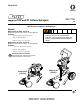
Operation 3A1775C Magnum X5 and X7 Airless Sprayers EN - For Portable Spray Applications of Architectural Paints and Coatings - Not for use in explosive atmospheres - Models: Magnum X5 (16J750) - Series A Maximum Working Pressure: 207 bar, 21 MPa (3000 PSI) Includes: •0.91 lpm (0.24 gpm) stand-mount sprayer •SG2 gun - Manual 312830 •0.635 cm (1/4 in) x 7.5 m (25 ft) hose • Use water-based or mineral spirit-type materials only. Do not use flammable materials.
Table of Contents Warnings . . . . . . . . . . . . . . . . . . . . . . . . . . . . . . . . . 3 Grounding Instructions . . . . . . . . . . . . . . . . . . . . . . 7 Thermal Overload . . . . . . . . . . . . . . . . . . . . . . . . 7 Component Identification (Magnum X5) . . . . . . . . 8 Component Identification (Magnum X7) . . . . . . . . 9 Operation . . . . . . . . . . . . . . . . . . . . . . . . . . . . . . . . 10 Pressure Relief Procedure . . . . . . . . . . . . . . . . 10 Pressure Adjustment . . . . . . .
Warnings Warnings The following warnings are for the setup, use, grounding, maintenance and repair of this equipment. The exclamation point symbol alerts you to a general warning and the hazard symbol refers to procedure-specific risks. Refer back to these warnings. Additional, product-specific warnings may be found throughout the body of this manual where applicable. WARNING GROUNDING This product must be grounded.
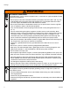
Warnings WARNING FIRE AND EXPLOSION HAZARD Flammable fumes, such as solvent and paint fumes, in work area can ignite or explode. To help prevent fire and explosion: • Do not spray or clean with flammable materials [flash points lower than 100° F (38° C)]. Use • • • • • • • • • • • • • water-based material or mineral spirits-type material only. For complete information about your fluid, request the MSDS from the fluid distributor or retailer.
Warnings WARNING SKIN INJECTION HAZARD High-pressure fluid from gun, hose leaks, or ruptured components will pierce skin. This may look like just a cut, but it is a serious injury that can result in amputation. Get immediate surgical treatment. • Do not spray without tip guard and trigger guard installed. • Engage trigger lock when not spraying. • Do not point gun at anyone or at any part of the body. • Do not put your hand over the spray tip.
Warnings WARNING PRESSURIZED ALUMINUM PARTS HAZARD Use of fluids that are incompatible with aluminum in pressurized equipment can cause serious chemical reaction and equipment rupture. Failure to follow this warning can result in death, serious injury, or property damage. • Do not use 1,1,1-trichloroethane, methylene chloride, other halogenated hydrocarbon solvents or fluids containing such solvents. • Many other fluids may contain chemicals that can react with aluminum.
Grounding Instructions Grounding Instructions 3. Do not use an extension cord with damaged ground plug. Recommended extension cords: Sprayer must be grounded. Grounding reduces the risk of static and electric shock by providing an escape wire for electrical current due to static build up or in the event of a short circuit. 1. This sprayer requires 220-240 VAC, 50/60 Hz 10A circuit with a grounding receptacle. Never use an outlet that is not grounded. ti7529b • 15 m (49.2 ft) 1.0 mm2 • 30 m (98.4 ft) 1.
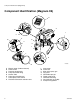
Component Identification (Magnum X5) Component Identification (Magnum X5) B A Z J C S Q G V H L K R P T D U ti15963b M A B C D G H J K 8 Electric motor (inside enclosure) Power switch Pressure control knob Pump fluid outlet fitting Suction Tube Prime tube (with diffuser) Prime/Spray valve control Fluid inlet connection and inlet valve L M P Q R S T V Z Inlet screen Paint hose SG2 airless spray gun Tip guard Reversible spray tip Trigger safety lever Gun fluid inlet fitting Gun fluid filter (in
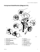
Component Identification (Magnum X7) Component Identification (Magnum X7) B W A J Z C K X H Q D S G V P T L R U A B C D G H J K L Electric motor (inside enclosure) Power switch Pressure control knob Pump fluid outlet fitting Suction Tube Prime tube (with diffuser) Prime/Spray valve control Fluid inlet connection and inlet valve Inlet screen 3A1775C M ti15964b M P Q R S T V W X Z Paint hose SG3 airless spray gun Tip guard Reversible spray tip Trigger safety lever Gun fluid inlet fitting Gun
Operation Operation Pressure Relief Procedure Pressure Adjustment Follow this Pressure Relief Procedure whenever you stop spraying and before cleaning, checking, servicing, or transporting equipment. 1. Align arrow on sprayer with spray symbol on pressure control knob. 1. Turn OFF power switch. ti2031a ti2018a 2. Turning knob right (clockwise) increases pressure at gun. 2. Place prime tube in waste pail. ti2032a ti2034a 3. Turn Prime/Spray valve to PRIME. 3.
Setup Setup 3. Connect other end of hose to sprayer fluid outlet fitting. Use wrench to tighten. 1. Turn OFF power switch. ti15965a ti2018a 2. Connect one end of grounded fluid hose to spray gun. Use a wrench to tighten. 4. Turn pressure control knob left (minimum pressure).
Priming Priming 5. Push pump priming button two times. For flushing storage fluid and loading pump and hose with paint. Before priming sprayer, follow Cleaning procedure, Steps 1-6, page 17. ti15972a 6. Turn ON power switch. Align arrow on sprayer and bucket symbol on pressure control knob. 1. Turn OFF power switch. ti2018a 2. Submerge suction tube in paint. ti2028a 7. When paint, without bubbles, starts to come out of prime tube, trigger gun and turn Prime/Spray valve to SPRAY.
Priming Install Tip and Guard on Gun Spraying Techniques 1. Engage trigger lock. Motor runs only when gun is triggered. Sprayer is designed to stop pumping when gun trigger is released. Getting Started ti8908a 2. Verify tip and guard parts are assembled in order shown. retaining nut Hold gun 30 cm (12 in.) from surface and aim straight at surface. Tilting gun to direct spray angle causes an uneven finish.
Priming Unclogging Spray Tip 5. When obstruction is cleared, engage trigger lock and rotate arrow-shaped handle back to SPRAY position. To avoid fluid splash back: • Never pull gun trigger when arrow-shaped handle is between SPRAY and UNCLOG positions. • Tip must be pushed all the way into guard. 1. To UNCLOG tip obstruction, engage trigger lock. ti9049a Point the arrow-shaped handle on the spray tip forward to SPRAY and backward to UNCLOG obstructions.
Selecting the Right Tip Selecting the Right Tip Tip Hole Size • Spray should be atomized (evenly distributed, no gaps or edges). Start at a low pressure setting, increase pressure a little at a time until paint atomizes. • Fluid flow rate is controlled by tip hole size. • The best tip hole size for fluid you are spraying is determined by type of coating and type of surface you are spraying. • Use large tip hole size when spraying thicker coatings.
Selecting the Right Tip Tip Number The last three digits of tip number (example 286413) contain information about hole size and fan width when gun is held 30.5 cm (12 in.) from surface being sprayed. Reversible Tip Selection Table Tip Part Number Fan Width 305 mm (12 in.) from surface Hole Size 286313 286413 286415 286515 286417 286517 152-203 mm (6-8 in.) 203-254 mm (8-10 in.) 203-254 mm (8-10 in.) 254-305 mm (10-12 in.) 203-254 mm (8-10 in.) 254-305 mm (10-12 in.) 0.33 mm (0.013 in.) 0.33 mm (0.
Cleanup Cleanup 5. While pump continues to stroke, remove trigger lock. Trigger gun into paint pail. Turn Prime/Spray valve to SPRAY. Continue to trigger gun until flushing fluid comes out of gun. Release trigger. 1. Engage gun trigger lock. ti2051a ti2048a NOTE: To minimize splashing, aim gun at inside wall of empty waste pail. 2. Turn OFF power switch. Turn Prime/Spray valve to PRIME. 6. Move gun to waste pail. Trigger gun until remaining flushing fluid is gone from flushing pail.
Cleanup Cleaning Gun Filter 3. Remove filter and clean it in compatible solvent. Perform Pressure Relief Procedure, page 10. 1. Engage gun trigger lock. ti2055a NOTE: Do not soak entire gun in solvent. Prolonged exposure to solvent can ruin packings. 4. Insert filter. ti2048a 2. Unscrew hose.
Cleanup Filling Sprayer with Storage Fluid Always pump storage fluid through pump system after cleaning. Water left in sprayer will corrode sprayer and damage pump. 1. Remove inlet strainer. Place suction tube in storage fluid bottle and prime tube in waste pail. 4. Turn ON power switch. ti2028a1 5. Align arrow on sprayer with roller symbol on pressure control knob. ti2058a 6. When storage fluid comes out of prime tube (5-10 seconds) turn OFF power switch. ti2057a 2. Turn Prime/Spray valve to PRIME.
Maintenance Maintenance Tips • Always clean tips with compatible solvent and brush after spraying. • Tip life: 57 liters (15 gallons) - 227 liters (60 gallons)* • Do not spray with worn tip. NOTICE Openings in shroud provide air for cooling mechanical parts and electronics inside. If water gets in these openings sprayer could malfunction or be permanently damaged. Caring for Sprayer Clean sprayer and accessories thoroughly after each use.
Troubleshooting Troubleshooting Problem Pump will not prime HINT: • Attempt to free check balls by Cause Prime/Spray valve set at SPRAY. Inlet screen clogged. Suction tube is not immersed. Inlet valve check ball stuck. pushing pump priming button. • Attempt to free check balls by tapping side of inlet valve as sprayer is stroking. • Strain paint before spraying. Outlet valve check ball stuck. Suction tube is leaking. Prime/Spray valve clogged. Keep sand and debris out.
Troubleshooting Problem Pump cycles but pressure does not build up. Cause Pump not primed. Inlet screen clogged. Suction tube not immersed. Paint pail empty. Suction tube has vacuum air leak. Pump check valves are dirty or damaged. Prime/Spray valve worn or obstructed with debris. Pump check ball stuck. Cannot pull gun trigger. Gun stops spraying. Gun trigger safety engaged. Spray tip clogged. Pump cycles but paint only dribbles or spurts when trigger is pulled. Pressure is set too low.
Troubleshooting Problem Sprayed paint runs down wall or sags. Sprayed paint is not covering. Pattern is inconsistent or leaving stripes. Cause Solution Going on too thick. Move gun faster. Use tip with smaller hole size. Use tip with wider fan. Move gun away from surface. Going on too thin. Move gun slower. Use tip with larger hole size. Use tip with narrower fan. Move gun closer to surface. Pressure set too low. Turn pressure control knob right to increase pressure.
Technical Data Technical Data X5 X7 Maximum fluid working pressure - sprayer 207 bar, 21 MPa (3000 psi) Sprayer inlet size 3/4 in. internal thread (standard garden hose USA) Sprayer outlet size 1/4 npsm external thread Electric motor (open frame universal motor) 1/2 hp 4.5 Amp 5/8 hp 4.5 Amp Sprayer weight only 6.1 kg (13.3 lb) 10.6 kg (23.3 lb) Length 36.0 cm (14.5 in.) 49.5 cm (19.5 in.) Width 31.5 cm (12.4 in.) 38.9 cm (15.3 in.) Height 45.5 cm (17.9 in.) 94.0 cm (37.0 in.
Notes Notes 3A1775C 25
Graco Standard Warranty Graco warrants all equipment referenced in this document which is manufactured by Graco and bearing its name to be free from defects in material and workmanship on the date of sale by an authorized Graco distributor to the original purchaser for use. With the exception of any special, extended, or limited warranty published by Graco, Graco will, for a period of twelve months from the date of sale, repair or replace any part of the equipment determined by Graco to be defective.