Installation instructions for: INTERCOOLED SUPERCHARGER SYSTEM 2005-2007 FORD MUSTANG 4.6L 3V Step-by-step instructions for installing the best in supercharger systems. PREMIUM FUEL REQUIRED ATTENTION! Your MAGNA CHARGER intercooler kit Is sensitive to corrosion! Take care of if by using 50/50 Anti-freeze with de-ionized water. 89-89-65-005 Rev F Magnuson Products Inc 1990 Knoll Drive, Ventura, CA. 93003 Phone (805) 289-0044 * Fax (805) 677-4897 magnusonproducts.com * magnacharger.
INSTALLATION MANUAL Magna Charger FORD 4.8 Liter 3V Engine, 2005-2007 MUSTANG Please take a few moments to review this manual thoroughly before you begin work: A quick parts check to make certain your kit is complete (See shipper parts list in this package). If you discover shipping damage or shortage, please call our office immediately. Take a look at exactly what you are going to need in terms of tools, time, and experience. Review our limited warranty with care.
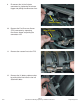
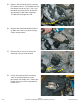
1. Relieve the pressure in the fuel tank by removing the cap and re-installing it. IMPORTANT! Ensure vehicle has 91 or higher-octane fuel in it prior to supercharger installation! 2. Disconnect the negative (-) battery clamp using a 7mm wrench. 3. Remove the Positive Crankcase Ventilation (PCV) line from the air tube by pressing the release trigger in the connector and pulling it free. Follow the line to its connection on the cam cover and remove the line completely from the motor. Release Trigger 4.
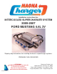
5. Loosen the air tube clamp at the air box using a 8mm nut driver or straight blade screwdriver 6. Remove the air tube completely from the vehicle. 7. Remove the Throttle Position Switch (TPS) connector by sliding the red release latch outward and pulling the connector free. 8. 9/07 Remove the Electronic Throttle Control (ETC) connector by sliding the red release latch outward and pulling the connector free.
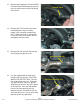
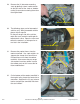
9. Disconnect the (8) fuel injector connectors by squeezing the release trigger and pulling the connectors free. Release Trigger 10. 9/07 Remove the Fuel Pressure Sensor (FPS) connector by squeezing the release trigger and pulling the connectors free. 11. Remove the vacuum line to the FPS. 12. Remove the (2) battery cable anchors by pulling them free from the fuel rail attachment bolts. Release Trigger Page 5 2005-2007 Ford Mustang Supercharger Installation Instructions magnacharger.
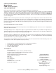
13. Remove the Evaporative Control (EVAP) line behind the throttle body by pressing in on the white release latch and pulling the line free. 14. Remove the PCV line from the intake manifold by pressing the release trigger in the connector and pulling it free. Follow the line to its connection on the cam cover and remove the line completely from the motor. 15. Remove the fuel line lock clip from the fuel rail by gently prying it free. Release Latch Fuel Line Lock Clip 16.
17. Remove the (4) bolts that secure the fuel rails to the intake manifold using a deep 8mm socket wrench. 18. Remove the fuel rails complete with injectors from the intake manifold, by pulling up firmly on the fuel rails. 19. At the rear of the intake manifold locate the electrical connector for the manifold servo- motor. 20. Press the release trigger and pull the connector apart. Release Trigger 9/07 Page 7 2005-2007 Ford Mustang Supercharger Installation Instructions magnacharger.
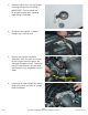
21. 9/07 At the rear of the intake manifold remove the brake vacuum hose by squeezing the ears of the clamp using a pair of pliers and pulling the hose free. 22. Remove the (5) bolts on each side of the intake manifold using a 10mm socket wrench. 23. Carefully lift the intake manifold free from the engine. 24. Carefully clean the cylinder head port faces and cover them with masking tape or clean shop towels.
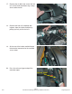
25. Depress the tensioner arm by inserting the square end of a 1/2” breaker bar into the square hole on the arm. Press the bar down to relieve tension on the belt and remove the belt from the pulleys. This belt will no longer be used. 1/2” Breaker Bar 26. Remove the Alternator bracket and the (4) bolts that secure it in place using a 10mm socket wrench 27. Remove the (2) nuts that secure the alternator using a 13mm wrench. Remove Nuts 28.
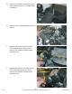
29. Remove the (2) alternator-mounting studs by placing a 6mm socket wrench on the hex ends of the studs or “doublenutting” them and unscrewing them from the engine block. Remove Studs Double Nutted Stud 30. The following steps are for Intercooled vehicles only! Non-intercooled vehicles please skip to step 58. On the passenger side of the vehicle, under the nose, locate the white plastic radiator drain valve. Open the valve and collect the coolant in a drain pan for reuse late in the installation.
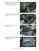
33. Remove the gray release latches from the elbow and insert them into the connector. 34. Remove the coolant manifold and the (4) bolts that secure it using a 10mm socket wrench. 35. Grasp the steel elbow on the bottom of the coolant manifold using a large set of pliers. Using a small torch or heat gun, apply heat to the bottom of the manifold were the steel elbow is inserted. Steel Elbow Torch or Heat Gun HEAT 36.
9/07 37. Allow the manifold to cool completely. Install the small 5/8” core plug supplied using a suitable drift and hammer in to the hole that the elbow was removed from. 38. Here is the core plug correctly installed in the bottom of the coolant manifold. 39. Locate the Engine Coolant Temperature (ECT) connector clipped to the steel coolant pipes in the engine valley. Disconnect it by squeezing the release trigger of the connector and pulling it apart. 40.
41. At the rear of the passenger side cylinder head, locate the bolt that secure the steel coolant pipes in place and remove it using a 13mm socket wrench. 42. Pull the coolant pipes up so you can remove the coolant hoses and clamps using a pair of pliers. 43. After removing the coolant hoses, gently lift the pipes up and back to remove them from the engine. Some additional engine coolant will be lost at this point, place a suitable drain pan under the transmission bellhousing to collect it. 44.
45. Place the coolant pipes in the soft jaws of a vice. Separate the (2) coolant pipes by cutting the connecting brackets using a hack saw. Cut Here 9/07 46. Use care when cutting, as the smaller diameter pipe will be re-used. 47. Here are the coolant pipes separated, and the smaller diameter pipe is now ready for re-installation. 48. Re-install the smaller diameter coolant pipe by first carefully starting the end on the engine block nipple. Secure the coolant pipe with the bolt previously removed.
49. Re-install the coolant hose onto the pipe using the original clamp. 50. On to the remaining coolant hose, install the 90-degree connector and the “elbow” hose supplied as shown. Secure the 90-degree fitting with the original clamp, and the elbow hose with the new spring clamp supplied. Coolant Hose Spring Clamp 90º Fitting “Elbow” Hose 51. Here is the 90-degree fitting and elbow hose installed.
53. Install the hose connector supplied into the ends of the hose. Note that the barb on the connector will point rearwards, towards the engine, away from the radiator. Secure the connector in the hose with the #18 clamps supplied but leave them loose so final adjustments can be done on the vehicle. 54. Here is the completed hose with the connector installed. To Manifold To Radiator 9/07 55. Re-install the water manifold. Torque the fasteners to 89 in-lbs using a 10mm socket and torque wrench. 56.
57. 58. Install the end of the elbow hose on to the barb of the new coolant hose connector with the spring clamp supplied. Position the connector and elbow hose so that the elbow hose can be routed beside the engine. Tighten the connector hose clamps. Refill the radiator reservoir with the coolant removed earlier. Here is the new drive belt idler pulley and mounting hardware. Hose Connector Barb Elbow Hose Idler Pulley Mounts Here Bracket Pulley Spacer Bracket Bolts Idler Pulley Bolt 9/07 59.
61. Install the idler pulley with its spacer into the remaining hole on the mounting bracket with the bolt supplied. Torque this bolt to 28 ft-lbs (38 Nm) using a 15mm socket and torque wrench. 62. Install the (2) new alternator brackets with the (4) original bolts. Torque them to 106 in-lbs (12Nm) using a 8mm and 10mm sockets and a torque wrench. Alternator Brackets 9/07 63.
65. Here is the tensioner with the stop removed. Ensure that there is no material left on the body of the tensioner where the stop previously was. Grind or file the body to make this area smooth and flat with the surrounding area of the body. This area must be flat and smooth. Removed Stop 66. Re-install the modified tensioner into it original location with its bolts. Torque the (3) bolts to 22 ft-lbs (30 Nm) using a 10mm socket and torque wrench. 67.
69. Install the two-throttle body-mounting studs removed in the previous step into the lower (2) holes on the supercharger inlet flange. Double-nut the studs, tighten them securely into the supercharger inlet flange and remove the nuts. Double-Nutted Stud 70. Carefully remove the throttle body gasket from the intake manifold. 71. Install the throttle body gasket into the groove in the inlet manifold flange. Gasket 72.
73. Carefully remove the (8) intake manifold gaskets from around the port openings on the bottom of the intake manifold. Gaskets 74. Clean and inspect the manifold gaskets removed from the original intake manifold. Install the gaskets onto the supercharger manifold. Note, the “tab” on the gasket and how it fits in the slot provided for it. Ensure that all (8) gaskets are installed correctly Gasket Tab 9/07 75.
77. Remove the FPS from the fuel rail by removing the (2) mounting bolts using a 8mm socket wrench. 78. Carefully install the FPS onto the fuel manifold using a small amount of the grease supplied on the sensor O-ring. Fasten the sensor using the (2) original mounting bolts. Torque the bolts using a torque wrench and a 8mm socket to 106 in-lbs (12Nm). 79. Connect (1) end of the 6” length of 1/4” hose supplied to the small barb located behind the bypass canister on the supercharger manifold.
81. Install the 10 intake manifold bolts into place on the supercharger manifold. Torque all manifold fasteners in (2) steps using a 10mm socket and torque wrench using the diagram shown in the next step. 82. Torque all manifold fasteners in (2) steps. In the first step torque the fasteners to 18 in-lbs (2Nm). In the second step torque to 89 in-lbs (10Nm) using the diagram shown. S/C 83. Here is the new drive belt routing diagram. Alt. Idlr Idlr W/P Idlr 3.0 Tensr.
84. Using a “breaker bar” or long 1/2” ratchet wrench, relieve the tension on the tensioner arm and install the new drive belt using the belt diagram provided. 1/2” Breaker Bar 9/07 85. Locate the Mass Air Flow (MAF) connector on the wiring harness. Remove the tape from tape form the harness back to the main branch. 86. On the MAF connector, locate the SOLID GRAY wire and the GRAY/RED wire. This is the Intake Air Temp (IAT) circuit. 87.
9/07 88. Remove the tape on the main branch of the wiring harness behind the MAF connector backs to about the #6 fuel injector branch. Locate the SOLID GRAY and the GRAY/RED wires previously cut from the MAF connector and pull them free from the harness to this point. You will be making a new branch on the wiring harness with these wires. 89. Tape the (2) short ends of the Gray and Gray/Red wire at the MAF connector to the harness as they will no longer be used.
92. 9/07 Install the new IAT sensor connector onto the IAT sensor located at the rear of the supercharger manifold. 93. Install the ETC connector onto the throttle body. 94. Install the TPS connector onto the throttle body. 95. Install the fuel pressure connector to the sensor on the fuel rail. Intake Air Temperature Sensor Page 26 2005-2007 Ford Mustang Supercharger Installation Instructions magnacharger.
96. Install all eight-fuel injector connectors onto the injectors. 97. Remove the air box cover by pulling the latches rearward and lifting up on the cover. Remove the air filter element. Note: A replacement element is supplied. Pull 98. 99. 9/07 Remove the air box from the vehicle by removing the mounting bolt using a 10mm socket wrench. Remove Carefully remove the MAF element from the air box cover by removing the (2) screws using a T-20 Torque driver.
100. Assemble the MAF element into the new air box cover with the original screws. Note the direction of the “FLOW” as shown on the MAF element-mounting flange, this should point towards the round opening of the new air box cover. MAF Element Air Flow 101. Here are the new air box cover latch components. There are components for (3) latch assemblies. Latch Base Plate Threaded Plate Mounting Screws 102.
104. Install the latch into place by passing the mounting screws through the latch, base plate and into air box 105. Install the threaded plate by threading the mounting screws into it. Tighten the screws securely. Note how the bottom edge of the threaded plate matches the contour of the air box. 106. Here is latch installed on the left side of the air box. 107. Install another latch using the described method on the rear of the air box as shown.
108. Finally install the last latch on the right side of the air box in the location shown. 109. Re-install the air filter element into the air box. 110. Install the new air box cover by engaging the (3) locating tabs on the rear of the air box. 111. Position the air box cover in place as shown and secure it by snapping the (3) latches down. 9/07 Page 30 2005-2007 Ford Mustang Supercharger Installation Instructions magnacharger.
112. Re-install the modified air box assembly into its original location. Tighten the mounting bolt securely using a 10mm socket wrench. 113. Install the MAF connector onto the MAF sensor. 114. Here is the air tube assembly and mounting components. 115. Locate the original air tube assembly. Inspect and squeeze the smaller, round (MAF) end to see if there is a vapor element installed.
116. Remove the clamp from the end of the air tube. Use a sharp knife or razor blade to cut the rubber of the air tube to free the vapor element. 117. Carefully remove the vapor element from the air tube. Vapor Element 118. Install the vapor element into the end of the new air tube as far as it will go. Next, slide the new “hump” hose over the element and onto the air tube. 119. Install the hose and clamps onto the air tube as shown. Do not tighten the clamps completely at this time.
120. Install the air tube assembly by sliding the round hose onto the air box cover connection first, then working the oval hose onto the throttle body. 121. With the air tube assembly installed, carefully tighten all (4) hose clamps. Note: The PCV barb. PCV Barb 122. Using a shop knife cut the plastic tubing on the original PCV lines to free the plastic end fittings. 123. Remove the brake vacuum hose where it meets the check valve on the brake booster.
124. Cut a 2” length of 3/4” vapor line from the length of hose supplied. 2” 125. Cut a 2-1/2” length of 3/8” fuel line from the length of hose supplied. 2-1/2” 126. Cut the length of 11/32” vacuum hose supplied into (2) pieces, (1) 7” long and the other hose 17” long. 17” 7” 127. Here are the components that will make up the driver side PCV/brake hose assembly. Note: The 3/8” “T” fitting and the 3/4” to 3/8” adaptor fittings are supplied.
128. Here is the driver side PCV hose assembled. 129. Install the 90-degree PCV fitting onto the barb located on the driver side cam cover. 130. Install the remaining end of the 11/32 vacuum hose on the barb to the brake booster check valve. 11/32” Vacuum Hose Check Valve 131. Install the vacuum hose onto the barb located on the driver side of the supercharger inlet manifold. EVAP Hose Barb Brake Hose Barb 9/07 Page 35 2005-2007 Ford Mustang Supercharger Installation Instructions magnacharger.
132. Locate the EVAP hose previously removed. Connect the hose to the upper barb on the supercharger inlet manifold. 133. Connect the EVAP hose to the upper barb located on the driver side of the inlet manifold as shown. EVAP Hose 134. Remove the fittings from the end of the passenger side PCV line. 135. Install the fittings removed in the last step into the remaining length of the 3/8” hose supplied. 9/07 Page 36 2005-2007 Ford Mustang Supercharger Installation Instructions magnacharger.
136. Connect the end of the new PCV line to the passenger side cam cover barb. Route the hose toward the front of the vehicle. 137. Connect the remaining end of the new PCV line to the barb on the side of the new air tube assembly. To Brake Booster 138. Here is a diagram of the hose routing. To EVAP Supercharger To Cam Arm Cover S/C Intake To Cam Arm Cover Throttle Body Air Tube Front of Vehicle 139. Install the fuel line connector onto the barb on the fuel manifold.
140. Install the fuel line lock clip onto the fuel manifold. Ensure that the fuel line is properly connected. 141. The following steps are for Intercooled vehicles only! Non-intercooled vehicles please skip to step 219. Remove the (6) push-rivets that secure the radiator shroud. 142. Remove the push-rivets by first prying up the center of the rivet using a small straight blade screwdriver and the remove the outer body of the rivet complete. 143. Remove the radiator shroud.
144. Raise the vehicle on an approved lift or jackstands. Locate the (7) fasteners that retain the lower splash shield. 145. Remove the (7) fasteners using a 6mm socket wrench. 146. Remove the lower splash shield from the vehicle. 147. In both of the front wheel wells remove the (3) screws that secure the inner plastic fender well using a crosshead screwdriver. 9/07 Remove Screws Page 39 2005-2007 Ford Mustang Supercharger Installation Instructions magnacharger.
148. In each of the front wheel wells remove the (3) push-rivets that secure the inner plastic fender well. (Left front shown.) 149. Remove the push-rivets by pulling up on the center portion and then removing the complete rivet assembly as shown. 150. Between the grille and headlight on both sides of the vehicle, remove the bolt on the top of the fascia. 151. Carefully remove the front plastic fender wells from both sides of the vehicle. Note: Where the front fascia meets the fender.
152. On the inside of the fender where the fender meets the fascia, remove the (2) nuts using a 10mm socket wrench. (The fascia has been removed in this photo for clarity.) Remove 153. Carefully pull the fascia forward a few inches to remove the final connections. 154. With the front fascia pulled forward a few inches, remove the fog light electrical connectors by squeezing the release triggers and pulling the connectors free. The front fascia can now be completely removed and set aside.
156. Squeeze the trigger on the electrical connector to remove it from the horns. Next, remove the horn from the original mounting bracket using a 10mm wrench. Remove Nuts 157. Using the original mounting nuts, mount the horns onto the new horn bracket supplied as shown. Tighten the mounting nuts securely using a 10mm wrench. 158. On the outside of the right (passenger side) frame rail, directly behind the bumper structure, make (2) 3/16” holes using a drill in the locations shown. 2-3/4” 7/8” 3” 159.
160. Here is the horn assembly installed. 161. Install the horn electrical connector. 162. Mount the intercooler pump relay in the location shown by passing a ty-strap through the hole in its mounting tab and through a hole in the upper cross member. Relay 163. Locate the ground connections on the top surface of the upper cross member. 9/07 Page 43 2005-2007 Ford Mustang Supercharger Installation Instructions magnacharger.
164. Remove the bolt from either ground connections using a 10mm wrench. Pass the bolt through the ring connector of the BLACK wire from the intercooler relay. Tighten the bolt securely. 165. Locate the black plastic fuse holder in the larger RED power wire. Install the 15-amp fuse supplied as shown, and then snap the attached cover on the fuse holder. 166. Remove the top cover of the fuse/relay center. 167. Remove the bolt securing the battery cable connector using a 10mm socket wrench.
168. Locate the 15-amp fuse located in the #40 position and remove it. Remove This Fuse 169. Install the “fuse-tap” supplied onto the fuse as shown. 170. Re-install the fuse into its original position with the fuse-tap installed. 171. Use a 1/8” drill to make a hole in the right rear corner of the fuse/relay center as shown. 9/07 Page 45 2005-2007 Ford Mustang Supercharger Installation Instructions Drill a 1/8” Hole magnacharger.
172. Route the YELLOW wire from the intercooler pump relay to the fuse/relay center. Insert the YELLOW wire through the new hole and into the fuse/relay center as shown. 173. Strip the insulation from the end of the YELLOW wire and crimp on the 3/16” female spade connector supplied. 174. Connect the female spade connector onto the end of the fuse-tap as shown.
176. Carefully remove the bumper front padding by removing the (4) plastic fasteners. Carefully Remove These Fasteners Bolts 177. Remove the (4) bumper fasteners by carefully prying the padding away from the bumper using a wide flat blade screwdriver or gasket scraper and then pulling the plastic fastener free. Pry gently! Fastener 178. On the passenger side of the vehicle, remove the inner (2) bumper mounting bolts using a 14mm socket wrench. Remove These Bolts 179.
180. Note how the threaded ends of the new bolts protrude from the back of the bumper structure. This is where the intercooler pump and bracket will mount. New Bolts 181. Here is the intercooler pump and its mounting hardware. Note that the (2) larger 8mm nuts will be used to mount the bracket and pump to the vehicle. 182. Attach the intercooler pump to the bracket as shown using Adel clamps shown using the 6 x 16mm bolts and nuts supplied. Tighten the bolts securely using a 10mm wrench. 183.
184. Route the Red and Black wires with the pump electrical connector from the pump relay forward to the intercooler pump. Plug the connector into the end of the pump. 185. Here is the Intercooler heat exchanger and this is the position it will mount on the vehicle. Note: The hose connections are on the bottom and the vent port on the top Pump Electrical Connector Vent Port Hose Connections 186. Locate the vent port fitting supplied.
188. Remove the power steering cooler mounting bracket bolts using a 10mm socket wrench. Allow the power steering cooler to carefully hang out of the way as you position the intercooler heat exchanger. Remove These Bolts 189. The intercooler heat exchanger will mount in front the air conditioning condenser and behind the power steering cooler. 190.
192. On the upper right front face of the air conditioner condenser, locate the small bolt shown and remove it using a 8mm socket wrench. Remove This Bolt 193. Position the heat exchanger mounting bracket over the bolt hole and pass the original bolt through the bracket and into the original hole. Tighten the bolt securely using a 8mm socket wrench. 194. Note that the heat exchanger mounting bracket aligns over a small bolt hole in the air conditioner condenser. Screw Location 195.
196. Install the length of 1/8” hose onto the small barb on the vent port fitting. Route the hose rearward towards the engine. The remaining end of the hose will be connected in a later step. 197. Here is the heat exchanger installed. Carefully re-attach the (2) pieces of bumper padding by inserting the (4) plastic fasteners into their original holes in the bumper structure. 198. Here is the intercooler filler bottle, cap, oil neck mounting clamp and bottle clamp.
200. Pass the mount screw through the hole in the mounting tab on the bottle and then back into its hole in the oil neckmounting clamp. Tighten the mount screw securely. (Shown removed from the oil neck for clarity.) Install the cap onto the filler bottle. 201. From the length of 3/4” hose supplied, cut a 30” length. Connect (1) end of the 32” length of hose to the lower left intercooler barb on the rear of the supercharger manifold.
204. Connect the short end of the elbow hose to the inlet barb of the intercooler pump. Secure the hose with the spring clamp supplied 205. Connect the remaining leg of the elbow hose to the front barb of the intercooler filler bottle with the spring clamp supplied 206. Route the heat exchanger vent hose up to the small barb on the filler bottle and connect it. 207. From the length of 3/4” hose supplied, cut a 12” length.
208. Connect the remaining end of the 12” hose to the barb passenger side (right) of the heat exchanger with the spring clamp supplied Barb on Passenger Side of Heat Exchanger 209. Connect (1) end of the remaining length of 3/4” hose to the barb on the driver side (left) of the heat exchanger with the spring clamp supplied. Barb on Driver Side of Heat Exchanger 210. Route this hose across the front of the vehicle and pass the radiator on the right side.
212. Using a 50-50 mixture of radiator coolant and de-ionized or distilled water, fill the intercooler system. Remove the cap from the intercooler filler bottle and fill the intercooler system until the fluid level is 1” from the bottom of threaded neck. Replace the cap after filling the system. Note that the system when full will hold about 1.5 gallons (6 liter.) You will not be able to will the system completely until a later step. 213. Here is the intercooler hose routing diagram.
216. Replace the radiator shroud and the (6) push-rivets. 217. Re-install the inner plastic fender wells with their original fasteners. 218. Install the belt routing, intercooler/ vacuum routing and the (1) premium fuel stickers to the top of the radiator shroud as shown. Belt Routing I/C & Vacuum Premium Fuel Routing Sticker Sticker Sticker 219. Install the second premium fuel sticker to the inside of the fuel door as shown.
220. Re-connect the negative (-) battery clamp using a 7mm wrench. 221. On the bottom edge of the driver side instrument panel, locate the OBDII service port. OBDII Service Port 222. Install the supercharged engine programming using the enclosed SCT program module. Important! Follow the instructions enclosed with the Program Module EXACTLY! 223. After loading the supercharged engine program, turn the ignition key to the ON position but do not start the vehicle.
224. Use only premium fuel, 91 octane or higher. Start the vehicle for 5 seconds and shut off. Check the supercharger installation for fuel leaks and supercharger belt alignment. Check radiator and intercooler fluid levels. 225. Test drive vehicle for the first few miles under normal driving conditions, listen for any noises, vibrations, engine miss fire or anything that does not seem normal. The supercharger does have a slight whining noise under boost conditions, which is normal.