MAG-WEDGE READER INSTALLATION AND OPERATION MANUAL Manual Part Number: 99821608 Rev 5 NOVEMBER 2005 REGISTERED TO ISO 9001:2000 1710 Apollo Court Seal Beach, CA 90740 Phone: (562) 546-6400 FAX: (562) 546-6301 Technical Support: (651) 415-6800 www.magtek.
Copyright© 1992-2005 MagTek®, Inc. Printed in the United States of America Information in this document is subject to change without notice. No part of this document may be reproduced or transmitted in any form or by any means, electronic or mechanical, for any purpose, without the express written permission of MagTek, Inc. MagTek is a registered trademark of MagTek, Inc.
LIMITED WARRANTY MagTek warrants that the products sold to Reseller pursuant to this Agreement will perform in accordance with MagTek’s published specifications. This warranty shall be provided only for a period of one year from the date of the shipment of the product from MagTek (the “Warranty Period”). This warranty shall apply only to the original purchaser unless the buyer is authorized by MagTek to resell the products, in which event, this warranty shall apply only to the first repurchase.
FCC WARNING STATEMENT This equipment has been tested and found to comply with the limits for a Class A digital device, pursuant to Part 15 of FCC Rules. These limits are designed to provide reasonable protection against harmful interference when the equipment is operated in a commercial environment. This equipment generates, uses, and can radiate radio frequency energy and, if not installed and used in accordance with the instruction manual, may cause harmful interference to radio communications.
TABLE OF CONTENTS SECTION 1. FEATURES AND SPECIFICATIONS.....................................................................................1 SECTION 2. INSTALLATION ......................................................................................................................5 HARDWARE INSTALLATION ..................................................................................................................5 CARD READING...........................................................................
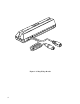
Figure 1-1.
SECTION 1. FEATURES AND SPECIFICATIONS The Mag-Wedge Reader connects in-line between a PC and its keyboard. It is intended to remain virtually invisible to both the keyboard and the PC until a card is read. When a card is read, the Mag-Wedge Reader takes over the interface to the PC and sends card data using the same scan codes used by the keyboard. The PC cannot distinguish between data from the keyboard and data from the Reader. Mag-Wedge Readers are available for connection to PS/2 and XT/AT type PC's.
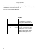
Mag-Wedge Reader Table 1-1. Part Numbers for Mag-Wedge Readers IBM XT Uses Existing Keyboard Cable Part Number Description 21080005 XT Tks 1,2 with CR. No PinPad Interface 21080006 XT Track 2 with CR. No PinPad Interface IBM AT Uses Existing Keyboard Cable* Part Number Description 21080020 AT Tracks 1,2 with CR 21080021 AT Track 2 with CR 21080012 Same as p/n 21080021 except no start and end sentinel output 21080022 AT Track 2,3 with CR IBM PS/1, PS/2 Compatible - Uses Existing Keyboard Cable*.
Section 1. Features and Specifications Specifications are listed in Table 1-2. Table 1-2. Specifications Color: Pearl White (Consult Factory for Other Colors) Power Requirements (without PINPad): 5V, 100mA max drawn from PC. Typical, 45mA. Dimensions Length: Width: Height: 6 1/2" 1 3/4” 1 5/8” Weight: 7 oz.
Mag-Wedge Reader 4
SECTION 2. INSTALLATION The Mag-Wedge Reader connections are very simple. There are two cables from the Reader, the male round connector plugs into a female connector on the PC where the keyboard originally went. The other connector plugs into the keyboard or keyboard cable. The RJ11 connector in the Reader is the connector for the cable from the PINPad. HARDWARE INSTALLATION To install the Mag-Wedge Reader proceed as follow: 1. Power down the PC 2.
Mag-Wedge Reader ERROR DETECTED: If the Reader cannot decode the data on the magnetic stripe, the LED on the Reader will glow red. If only one track of data can be decoded, that track will be transmitted and displayed. The red LED will be lit for the other track. In all cases except at power up, the red LED will only remain lit for two seconds. If the Reader does not respond as described above, make a note of the prompts or error messages on the display and the status of the LED on the Reader.
SECTION 3. OPERATION After the Mag-Wedge Reader is properly installed, power up the PC as usual. An LED on the Reader should momentarily illuminate an orange color. It will then quickly change to a red color and start blinking. The Reader determines the type of PC it is attached to by checking the commands the PC sends to the keyboard when powering up. The LED then illuminates a green color instead of blinking red.
Mag-Wedge Reader Enable PINPad Communication (Hex Al) - Default This command will activate the PINPad and allow the Reader to communicate with the PINPad. It will set the non-encrypting PINPad in a digit mode, or reset the encrypting PINPad. Enable Card Reading (Hex A2) - Default This command will activate the Reader, turn the LED on (green color) and allow the Reader to read the card. After the card is read, the card data will be sent to the PC.
Section 3. Operation EPP ACTIVE EPP, READER ACTIVE EPP, KEYBOARD ACTIVE EPP, READER. KEYBOARD ACTIVE NON EPP ACTIVE NON EPP, READER ACTIVE NON EPP, KEYBOARD ACTIVE NON EPP, READER, KEYBOARD ACTIVE READER ACTIVE KEYBOARD ACTIVE READER, KEYBOARD ACTIVE ALL DEVICES INACTIVE RESPONSE CODES AND TIMING K= Acknowledge O= No PINPad attached P=PINPad is attached, but disabled After receiving a valid command from the PC, the scan code "K" will be sent to the PC.
Mag-Wedge Reader 2) All keys on the keyboard are classified as make/break, which means when a key is pressed, the keyboard sends a make code for that key to the keyboard controller. When the key is released, its break code is sent. The time between the make code and the break code of a key pressed varies depending on how long a key is pressed, normally it should not exceed 500 milliseconds.