MODEL MT-215 TTL SINGLE OR DUAL HEAD INSERTION READER TECHNICAL REFERENCE MANUAL Manual Part Number 99875113 Rev 12 JUNE 2006 REGISTERED TO ISO 9001:2000 1710 Apollo Court Seal Beach, CA 90740 Phone: (562) 546-6400 FAX: (562) 546-6301 Technical Support: (651) 415-6800 www.magtek.
Copyright© 1998-2006 MagTek®, Inc. Printed in the United States of America Information in this document is subject to change without notice. No part of this document may be reproduced or transmitted in any form or by any means, electronic or mechanical, for any purpose, without the express written permission of MagTek, Inc. MagTek is a registered trademark of MagTek, Inc.
LIMITED WARRANTY MagTek warrants that the products sold to Reseller pursuant to this Agreement will perform in accordance with MagTek’s published specifications. This warranty shall be provided only for a period of one year from the date of the shipment of the product from MagTek (the “Warranty Period”). This warranty shall apply only to the original purchaser unless the buyer is authorized by MagTek to resell the products, in which event, this warranty shall apply only to the first repurchase.
FCC WARNING STATEMENT This equipment has been tested and found to comply with the limits for Class B digital device, pursuant to Part 15 of FCC Rules. These limits are designed to provide reasonable protection against harmful interference when the equipment is operated in a residential environment. This equipment generates, uses, and can radiate radio frequency energy and, if not installed and used in accordance with the instruction manual, may cause harmful interference to radio communications.
TABLE OF CONTENTS SECTION 1. FEATURES AND SPECIFICATIONS --------------------------------------------------------------------- 1 FEATURES ............................................................................................................................................... 1 CONFIGURATIONS ................................................................................................................................. 2 RELATED DOCUMENTS ...............................................................
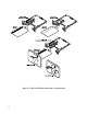
Figure 1-1.
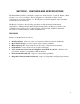
SECTION 1. FEATURES AND SPECIFICATIONS The Model MT-215 TTL is a manually operated two-track insertion, or push-in, Reader, which may have one or two read heads. Three configurations of the head(s) and two bezel configurations are shown in Figure 1-1. The Reader can read the magnetic stripe in both the forward and reverse directions.
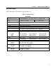
Model MT-215 TTL Single or Dual Head Insertion Reader CONFIGURATIONS Table 1-1 lists the part numbers, head mounted position, bezel type, and forward or reverse read. Table 1-1.
Section 1. Features and Specifications SPECIFICATIONS The specifications for the Reader are listed in Table 1-2. Table 1-2.
MT-215 TTL, Single or Dual Head Insertion Reader 4
SECTION 2. INSTALLATION This section describes cabling information, mounting dimensions and timing. PIN LIST AND CONNECTORS Table 2-1 lists the connector pins and the required mating Connector. Table 2-1.
MT-215 TTL, Single or Dual Head Insertion Reader MOUNTING Figure 2-1 shows the dimensions for mounting when using a flat-faced MagTek Bezel. Figure 2-2 shows the dimensions for mounting when using an extended MagTek Bezel. In these configurations, the top view and the side view show the head mounted under the PCB with connector J2 used. The other head configurations are shown in Figure 1-1.
Section 2. Installation of Bezel Figure 2-1.
MT-215 TTL, Single or Dual Head Insertion Reader .5 .72 .830 3.35 Figure 2-2.
Section 2. Installation Figure 2-3. Board Layout and Cable Connections Note The jumpers shown in Figure 2-3 are used only on the old PCB assembly (21063528); there are no jumpers on the new PCB assembly (21063548). J3 Connector for P/N 21065113 is a 9-pin connector with pins 10 & 11 removed.
MT-215 TTL, Single or Dual Head Insertion Reader CARD INSERTION AND ORIENTATION The Reader can be mounted in two positions as shown in Figure 2-4. On the left panel of the illustration, the card is inserted with the magnetic stripe to the left. On the right panel of the illustration, the card is inserted with the magnetic stripe up. These are the mounting positions that permit any foreign object inserted into the slot to drop out of the reader.
Section 2. Installation TIMING FOR BACK SENSOR AND CARD PRESENT Figure 2-5 shows the timing for the Back Sensor and the Card Present signals. The card is read in both directions (on insertion and withdrawal), but the data is active on withdrawal.
MT-215 TTL, Single or Dual Head Insertion Reader TIMING FOR DATA AND STROBE Figure 2-6 shows the timing for Data and Strobe. The timing shown is for active data (see Figure 2-5). NOTE 1 CARD PRESENT 0 0 0 0 0 0 1 DATA 1 0 0 1 1 1 NOTE 2 STROBE STROBE WIDTH APPROXIMATELY 25-50% OF BIT TIME NOTE 3 BIT TIME NOTES 1. TIME OUT OF THE CARD PRESENT SIGNAL OCCURS WITHIN APPROXIMATELY 150 MS FROM THE LAST STROBE TRANSITION. 2. DATA IS VALID 1.0 μS (MINIMUM) BEFORE THE NEGATIVE EDGE OF STROBE. 3.
Section 2. Installation Data The Data signal is valid while the Strobe is low. If the Data signal is high, the bit is a zero. Strobe The Strobe signal indicates when Data is valid. It is recommended that Data be loaded by the user with the leading edge (negative) of the Strobe.
MT-215 TTL, Single or Dual Head Insertion Reader 14
APPENDIX A. BEZEL DESIGN The engineering drawing in this section is for customers interested in designing their own bezel. The example shown is a typical design from MagTek. Please note that the bezel is an active part of the Reader; therefore the bezel design is important for card alignment and the performance of the Reader.
MT-215 TTL, Single or Dual Head Insertion Reader Figure A-1.
Appendix A. Bezel Design Figure A-2.
MT-215 TTL, Single or Dual Head Insertion Reader Figure A-3.
Appendix A. Bezel Design Figure A-4.
MT-215 TTL, Single or Dual Head Insertion Reader 20