
User`s manual


19
Magtrol Model DSP6001 Dynamometer Controller
Chapter 3 – Installation/Configuration
SETUP
3.2.2 HyStereSiS DynaMoMeter SetUp
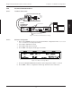
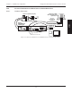
3.2.2.1 Hardware Connection
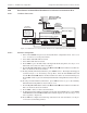
DYNAMOMETER / TSC1
AUX / TSC2
SUPPLY 2
SUPPLY 1
RS-232C
GPIB/IEEE–488
BRAKE
ACCESSORY
TORQUE–SPEED
OUTPUT
CTRL OUT
BRAKE FUSE
CAUTION: DOUBLE POLE FUSING
75VA 50/60Hz
EARTH
GROUND
FUSE (5×20mm):
120V UL/CSA 800mA 250V SB
240V IEC 315mA 250V T
(5×20mm):
UL/CSA 1.25A 250V SB
IEC 1A 250V T
MAGTROL, INC. BUFFALO, NY
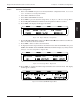
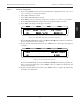
No Connection
Hysteresis on TSC1 only
AC Mains
Motor
Under
Test
Hysteresis Dynamometer (HD)
DSP6001
DYNAMOMETER
CONTROLLER
GPIB
RS-232
or
PC
M-TEST
Figure 3–8 Hysteresis Dynamometer Setup
3.2.2.2 Software Configuration
1. Turn on the DSP6001 and proceed to the dynamometer configuration menu. See Section
3.2.1 – Dynamometer Configuration Menu.
2. Select TSC1 until HD is reached.
3. Select TSC2 until AUX is reached.
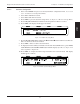
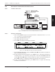
4. Press SHIFT. The display should appear as follows:
POWER
BRAKE STATUS SET POINT SET POINT P I D
TORQUE SPEED STATUS
Figure 3–9 Hysteresis Setup Menu
5. Press the TORQUE UNITS button until the desired input unit for TSC1 is reached.
6. Press SHIFT 3 times to complete the initial setup and return to the main menu.