
User`s manual

64
4. Connections / Configuration
4.1 CONNECTION TO MAGTROL MOTOR TESTING ELECTRONICS
The connection and configuration of the Magtrol DES Power Supply, TSC Torque/Speed Conditioner
and DSP Dynamometer Controller are described in the corresponding User's Manuals for each unit.
These manuals can be found on Magtrol's User Manual CD-ROM (delivered with your dynamometer)
and can also be accessed at Magtrol's Web site: www.magtrol.com. Refer to these documents for
additional information on connecting the WB/PB Series Dynamometer to Magtrol motor testing
electronics.
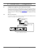
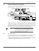
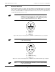
4.1.1 m
AnuAl teSt conFigurAtion
In a manual test configuration, all test parameters must be manually entered into the DSP Dynamometer
Controller. Data acquisition is then carried out manually.
DYNAMOMETER / TSC1
AUX / TSC2
SUPPLY 2
SUPPLY 1
RS-232C
GPIB/IEEE–488
BRAKE
ACCESSORY
TORQUE–SPEED
OUTPUT
CTRL OUT
BRAKE FUSE
CAUTION: DOUBLE POLE FUSING
75VA 50/60Hz
EARTH
GROUND
FUSE (5×20mm):
120V UL/CSA 800mA 250V SB
240V IEC 315mA 250V T
(5×20mm):
UL/CSA 1.25A 250V SB
IEC 1A 250V T
MAGTROL, INC. BUFFALO, NY
Excitation
Torque
TSC 401
Torque-Speed
Conditioner
DES Power Supply
Speed
Eddy-Current (WB)
OR Powder Brake (PB)
Dynamometer
DSP6001 Dynamometer Controller
Figure 4–1 Manual Test Configuration