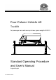
Four-Column Vehicle Lift Trucklift for passenger cars and vans up to max.
Trucklift EDITION Version 3 of the 22.10.1997 dated D1 3602BA1-GB03 Software Version from 4.3 © MAHA GMBH & CO. KG. All rights reserved. Any reproductions of this document, partial or complete, are only allowed with prior consent of MAHA GmbH & Co. KG. All rights reserved in cases of patent granting or registration of design. The contents of this version have been checked with great care. However, errors cannot be fully excluded. Please contact MAHA should you find errors of any kind.
Trucklift TABLE OF CONTENTS 1 Safety Instructions .................................................................................................... 1 1.1 1.2 1.3 1.4 2 Description ................................................................................................................ 5 2.1 2.2 2.3 2.4 3 Controls.......................................................................................................................................... 9 Vehicle Tracks ..........................
Trucklift IV
Trucklift 1 Safety Instructions 1.1 Safety Information Safety Instructions are provided to warn about dangerous situations and to help avoid injury to people. The truck lift is only to be used for its intended purpose as described in the operating instructions! Only trained authorized personnel may operate the truck lift.
Trucklift 1.2 Safety Instructions Further Information At installation pay attention to the following: Standard lifting platforms may not be operated in washing halls, rooms with high humidity or outdoors! The lifting platform must be protected from any form of water splashing! Never clean the lifting platform with high pressure cleaners or steam cleaners! In rooms with very low ceilings it is recommended to install a ceiling light barrier. This can be ordered from the manufacturer.
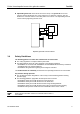
Fehler! Verweisquelle konnte nicht gefunden werden. Trucklift Adjustable guard rails around the lift and on the ramps. The guard rails on the four columns must be adjusted in such a way, that there is a clearance of approx. 150 mm between the extension and the connection plates of the column. The adjustable guard rail can be locked by tightening the M 8 screw. 150 Adjustable guard rails on all four columns 1.
Trucklift 4 Safety Instructions D1 3602BA1-GB03
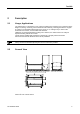
Trucklift 2 Description 2.1 Usage, Applications The TRUCKLIFT 8 / TRUCKLIFT 10 is a device for lifting motor vehicles up to a maximum gross weight of 8,000 kg / 10000 kg, with a maximum load of 6000 kg / 6600 kg permitted on any pair of columns. The maximum lifting height of the unit is 2,1 m, making it easy to work on the underside of the vehicle, even for taller staff members. TRUCKLIFT is designed primarily for lifting vans.
Trucklift 2.3 Descriptions Specifications Max. rated load in t Trucklift 8 Trucklift 10 8 10 Machine weight in kg 3500 Column height HS in mm 2650 Max. lifting height Ho in mm 1975 Height above ground surfaceFehler! Textmarke nicht definiert. Hu in mm Height to guard rail lower edge HB in mm 200 5810 Overall height HG in mm 5850 Inside column width BL in mm 3200 Max.
Trucklift 3 Installation 3.1 General Information TRUCKLIFT is normally installed by the manufacturer's own trained technicians. However, the lift can also be installed by the operator's own technical staff, provided that they are properly trained, with the necessary skills. It is important that they should have experience in the proper use of composite dowels and the proper installation of the electrical connections in accordance with the VDE regulations. 3.
Trucklift 3.3 Installation Foundations The concrete used for the foundations must be at least grade B25 and reinforced. Because of the anchoring dowels used, the concrete base slab must also have a minimum thickness of 200 mm. The operator must provide evidence of the base slab load bearing capacity. The foundations plan is also available from MAHA.
Trucklift 4 Operation 4.1 Controls The TRUCKLIFT unit has four controls. The main switch is used to turn the entire system on and off, and also doubles as an emergency off switch. Vor Öffnen des Gerätes Haupschalter ausschalten! Sicherheitsbestimmungen 1 The main switch must always be easily accessible. Bedienung: 0 Its position should never be changed. The light switch is identified by a light symbol. Turn this switch to the right to switch the light on.
Trucklift 4.2 Ôperation Vehicle Tracks The vehicle tracks can be moved laterally on the crossbars to adjust the width to match the track width of the vehicle to be lifted. Normally, you will only need to adjust the left track. Track to be adjusted To adjust the track width, first remove the retaining pins at the front and rear. Then move the track in the desired direction by inserting a lever in the retaining lug and levering against one of the holes in the perforated section below.
Operation 4.3 Trucklift Driving onto the Lift The control console is mounted on lifting column 1. The main switch is on the side of the console. Turn this switch to position 1 to turn on the power. The lift is then ready for operation. 1 0 The main switch doubles as the emergency off switch. In emergencies, simply turn the switch to the 0 position to switch off the lift! Remove all tools, chocks, stands etc. from the working area of the lift. 1. 2.
Trucklift 4.4 Ôperation Lifting You can lift the vehicle once it is properly positioned on the lift and secured against rolling away. To start the lift, press the '###' button. The lift stops as soon as you release the button.
Operation 4.6 Trucklift Lowering Sicherheitsbestimmungen Before lowering, always make absolutely sure that nobody is in the working area of the lift! Bedienung: Remove all tools, chocks, stands etc. from the working area of the lift. Vor Öffnen des Gerätes Haupschalter ausschalten! Press the 'Ä' key until the platform is in its lowest position. The lift stops automatically in its starting position. 4.
Trucklift 14 Ôperation D1 3602BA1-GB03
Trucklift 5 Maintenance, Troubleshooting 5.1 Maintenance Regular maintenance is necessary to ensure reliable operation of the lift and a long service life. a) The support arm extension and the support disc threading should be well greased. It is recommended to use lithium soap grease. The oil level of the oil pan should be checked quarterly. It is located on the carriage slides behind the spindle cover sheet.
Trucklift Maintenance, Troubleshooting c) Wear and tear on the support nut must be checked annually. Remove the plastic cap from the spindle cover sheet and move the carriage slides so that the control drill holes lines up with the window. If there is no visible gap this is an indicatioin that the support nut is worn down beyond the permissable limit. The support nut must be replaced. The gap is approximately 2 mm. ex factory.
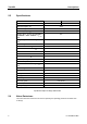
Maintenance, Troubleshooting 5.3 Trucklift Troubleshooting Checklist The following checklist will help your service technicians to locate faults in the event of problems. Problem When lifting, lift stops of its own accord at an arbitrary height. The LED on the circuit board lights up (see ill. on next page). Possible cause a) Excessive load on the lift. b) The distance between the pulse encoder and the drive pulley is too great.
Trucklift Maintenance, Troubleshooting Problem Possible cause Remedy The lift stops at a height of a) The distance between the a) Check the wear of the bearing approx. 260 mm catch nuts and the jackscrew nuts. (measured from the floor to bearing nuts is too small. b) Check the distance between the lower edge of the b) A proximity switch is defective the proximity switches and the carriage). switching cams on the frame or its setting is incorrect. The lift can only be and on the catch nuts .5 mm).
Maintenance, Troubleshooting Trucklift DIP RESET LED 1234 470nJ o63 Reset ON DIP 470nJ o63 Ver. KEB 470nJ o63 Appl. K3 K4 K7 MK1 470nJ o63 470nJ o63 LED K8 MK1 470nJ o63 470nJ o63 470nJ o63 470nJ o63 K1 1 0 K5 K2 1 0 1 0 K6 MK1 1 0 S2.2 S3.2 Q1 PE 230V 50/60Hz 18V 0,25A 5.
Trucklift 20 Maintenance, Troubleshooting D1 3602BA1-GB03
Trucklift 6 Warranty, Service 6.1 Warranty Subject to the provisions of their General Terms and Conditions of Business, Maschinenbau Haldenwang (MAHA) undertakes to repair or replace any defective components free of charge during the warranty period if the product is sent to MAHA – either directly or through an authorised MAHA dealer – or if the product is repaired or installed by authorised personnel. This warranty is only provided for products installed by authorised personnel.
Trucklift 6.3 Warranty, Service Service MAHA has customer service offices in many countries all over the world. You can contact these offices at any time to obtain answers to any questions you may have regarding MAHA products. If your product needs repair you can always contact your dealer, or you can contact MAHA directly. A charge will be made for repairs after the end of the warranty period.