OPERATION MANUAL ATX-3 Automatic Transmission Fluid Exchanger WARNING DO NOT pour anything except new transmission fluid into the fill port. Serious damage will result. The ATX-3 must be connected to a FULLY CHARGED 12 volt battery. This should be the battery in the vehicle being serviced. Do not use a battery charger to power the ATX-3. Use of undercharged batteries and battery chargers will damage the ATX-3 and void the warranty.
TABLE OF CONTENTS Component Description . . . . . . . . . . . . . . . . . . . . . . . . 2 Safety Precautions . . . . . . . . . . . . . . . . . . . . . . . . . . . 3 Keypad Functions . . . . . . . . . . . . . . . . . . . . . . . . . . . . 4 Cooler Mode Connecting to the Transmission System . . . . . . . . 6 Flush . . . . . . . . . . . . . . . . . . . . . . . . . . . . . . . . . . . . 8 Drain Pan . . . . . . . . . . . . . . . . . . . . . . . . . . . . . . . . 8 Fluid Exchange . . . . . . . . . . . . . . . . .
COMPONENT DESCRIPTION Unpack all components. Use laminated placard to verify fitting adapter quantities. Contact RTI if any items are missing or damaged.
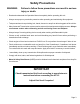
Safety Precautions WARNING: Failure to follow these precautions can result in serious injury or death. • Read and understand the Operation Manual completely before operating this unit. • Always wear proper eye and skin protection when operating and maintaining this equipment. • Take precautions to keep clothing, hair, hands, hoses etc. away from all moving parts of the vehicle. • Many Automatic Transmission systems can be extremely hot and operate at high pressures.
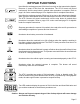
KEYPAD FUNCTIONS 560-80414-00 The ATX-3 is an automatic transmission fluid exchanger featuring state-of-the-art electronic controls with digital weight scales measuring the automatic transmission fluid coming into and going out of the machine. Operation of the ATX-3 is intuitive and very easy to master. Transmission fluid is removed from vehicle and filtered before collecting in the ATX-3 used fluid tank.
KEYPAD FUNCTIONS Used after the exchange process if fluid level is too high on the transmission dipstick. Removes ½ quart of fluid from the transmission. The ATX-3 buzzer will sound continuously until the stop button is pushed when procedure is complete. Refer to page 9 for cooler mode and page 13 for dipstick mode for complete instructions. Used after the exchange process if fluid level is too low on the transmission dipstick.
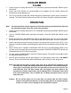
COOLER MODE CONNECTING TO THE TRANSMISSION SYSTEM Transmission Cooler Lines 560-80414-00 Radiator Fitting Adapters 12 inch 90° Adapter Hose 12 inch Straight Adapter Hose IMPORTANT Check transmission fluid level according to manufacturer’s instructions before connecting the ATX-3 Adjust fluid level if required 1. Add desired amount of transmission fluid to the new fluid tank through the ATX-3 fill port. Monitor fluid level in the ATX-3 with the LED readouts or with fluid sight indicators. 2.
COOLER MODE CONNECTING TO THE TRANSMISSION SYSTEM 3. Select and install proper fitting adapters to disconnect points. Use closest matching adapter and o-ring to seal any leaks if exact matching adapter can not be found. In some cases it may be easier to use one of the open end rubber hose adapters on the disconnected male fitting on the cooler line then to select the matching adapter. 4. Connect 12 inch adapter hoses to fitting adapters. 5.
COOLER MODE FLUSH 1. Vehicle engine is running and the ATX-3 is connected as previously described, READY light is illuminated. 2. Slowly add Flush Solution as recommended by the supplier into the vehicle through the transmission system dipstick port. 3. The ATX-3 will now circulate the solution through the transmission system until a procedure is selected. The Flush Solution will be removed from the system during the exchange procedure.
COOLER MODE FLUID EXCHANGE (4,8,12,16,20 QUARTS) 1. Vehicle engine is running and the ATX-3 is connected as previously described, READY light is illuminated. 2. Determine vehicle transmission fluid capacity from the vehicle operator or service manual. 3. Light on COOLER MODE button should be illuminated. Press the corresponding QUART button, always round up (for example if vehicle capacity is 6.5 quarts an 8 quart exchange would be selected). 4.
DISCONNECTING FROM THE TRANSMISSION SYSTEM - Caution Hoses, fitting adapters and the engine may be extremely hot. Use extreme caution when disconnecting. 1. Turn vehicle engine off. READY light should go off. Make sure READY light is OFF before proceeding. 2. Disconnect ATX-3 from the vehicle battery. 3. Disconnect 10 ft black and red hoses from the 12 inch adapter hoses. 4. Disconnect 12 inch adapter hoses from fitting adapters connected to the transmission system. 5.
DIPSTICK MODE CONNECTING TO THE TRANSMISSION SYSTEM IMPORTANT Check transmission fluid level according to manufacturer’s instructions before connecting the ATX-3 Transmission must be up to operating temperature Adjust fluid level if required Dipstick Notch Dip Tube Hose 560-80414-00 Slide Indicator 1. Remove transmission dipstick. 2. Hold notched end of Dip Tube Hose even with the end of the dipstick as shown above. 3. Position the slide Indicator so that is even with the cap end of the dipstick.
7. Connect red (positive) clamp on power cable to red (positive) terminal on vehicle battery. Connect the black (negative) clamp to a ground on vehicle frame. All lights on keypad should illuminate for one second and buzzer should pulse. If not, check connections and make sure REVERSE POLARITY light is not illuminated. WARNING: 8. Handle battery connection cable with extreme caution. Batteries generate explosive gases during normal operation.
6. Start the engine and then press the START ENGINE button. There will be 10 second delay after START ENGINE button is pressed to allow the new fluid to intermix with fluid in transmission system. After 10 seconds, the exchange will continue. 7. There is a 10 second pause after each refill. 8. If machine is unable tor retrieve more than 0.4 of a quart from the pan while engine is running, the Flo Err (Flow Error) message will be displayed and process needs to be aborted.
EMPTY USED Common for both modes 1. Connect red (positive) clamp on ATX power cable to red (positive) terminal on vehicle battery. Connect the black (negative) clamp to a ground on vehicle frame. Vehicle engine is turned OFF. The ATX-3 10 ft black and red hoses must be disconnected from the transmission. READY light is off. 2. Place end of 8 ft black hose (left side of ATX-3) in bulk used fluid container. Attach short black adapter hose with open end to coupler on end of 8ft black hose. 3.
MAINTENANCE The ATX-3 will provide many years of reliable service if properly maintained. The following checklist will ensure that the ATX-3 will run at peak efficiency and present an image to your customers that your shop performs high tech transmission services. 1. Use tool tray for storage of tools and adapters only. 2. Keep the exterior surface clean. Use a mild all purpose cleaner to wipe transmission fluid and dirt off the cabinet. 3.
ATX-3 Calibration The ATX-3 is a high-tech, electronically controlled machine for exchanging transmission fluid. The ATX3 is connected in series with the transmission fluid flow at the cooler hose. The vehicle transmission pump then pumps used fluid into the ATX-3 used fluid tank and the ATX-3 pumps new fluid to the transmission from the tank of new fluid in the ATX-3. Transmission pumps vary in their flow rate from vehicle manufacturer to manufacturer.
CALIBRATION OF LOAD CELLS The ATX-3 has two tanks, each mounted on a load cell. One tank is for new fluid and one is for used fluid. Each tank is permanently bolted to a load cell platform which can not be removed from the unit. The calibration procedure below must be performed for both load cells. Never calibrate only one load cell as an imbalance may occur and the ATX-3 will not operate correctly. 1. Remove the rear panel. 2.
PARTS IDENTIFICATION ATX-3 Part No. 5a 1 2 1 024-80119-00 Keypad Overlay 2 024-80121-00 Circuit Board (12VDC) 3 300-80075-00 Manifold Assembly 4 026-80250-00 Sight Glass 1/4" FPT w/screen 026-80248-00 Filter Mesh Cylinder 80 SS 026-80247-00 026-80248-00 Glass Sight 3/8" Barb Plastic w/clear Bowl Filter Mesh Cylinder 80 SS 5a 300-80028-00 Pressure Gauge 6 021-80164-00 Deck Fill Assembly ATX 7 022-80111-00 Pressure Switch 4-6 psig SPST 8 300-80033-00 Pump Gear .
FLOW DIAGRAM Page 19
Wiring Diagram Page 20
EC Declaration of Conformity for Machinery Directive 98/37/EC RTI Technologies, Inc.