OPERATION MANUAL MCX-1 Multiple Coolant Exchanger LOW & ER OVE RAD RFL IAT OW OR E MP TY OFF WA STE TAN K FIL E XCH L RAD A NG IAT E CO OR OLA & OV NT ERF OR LOW OF F LOW & E MP TY WA ER OV RAD ERF IAT LOW OR OFF STE TAN K EXC HA & NG FIL L OV RAD ERF IAT LOWOR E CO OLA NT RTI Technologies, Inc. 4075 East Market St. York, PA 17402 USA 800-468-2321 www.rtitech.
TABLE OF CONTENTS Component Description . . . . . . . . . . . . . . . . . . . . . . . 2 Safety Precautions . . . . . . . . . . . . . . . . . . . . . . . . . . . 3 Set-up . . . . . . . . . . . . . . . . . . . . . . . . . . . . . . . . . . . . . 4 Connection to Power . . . . . . . . . . . . . . . . . . . . . . . . . 5 Lowering Coolant Level . . . . . . . . . . . . . . . . . . . . . . . 6 Connecting to the Coolant System . . . . . . . . . . . . . . . 7 Special Hookups . . . . . . . . . . . . . . . . . . . . .
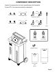
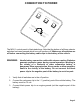
COMPONENT DESCRIPTION Unpack all components and verify quantities per this illustration. Contact RTI if any items are missing or damaged.
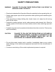
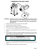
SAFETY PRECAUTIONS WARNING: FAILURE TO FOLLOW THESE PRECAUTIONS CAN RESULT IN SERIOUS INJURY OR DEATH. C Read and understand the Operation Manual completely before operating this unit. C Always wear proper eye and skin protection when operating and maintaining this equipment. C Take precautions to keep clothing, hair, hands, hoses, etc. away from all moving parts on the vehicle. C Automotive cooling systems can be under pressure and extremely hot.
SET UP Green Hose Black Hose LO & WE R OV RA ER DIA FLO W TO R EM PTY WA OF F STE TA NK FIL OF F EX CH L RA AN DIA GE TO CO R & OL OV ANT ER OR FLO W LO WE & OV R RA ER DIA FLO TO W R EM PTY WA STE TA OF F NK EX FIL & CH AN GE L RA OV DIA ER FLO TOR W CO OL AN T New Coolant Green Hose Tank Cap & Plug Quick Coupler New Coolant Tank (Small) The MCX-1 has two tanks (plus an extra New Coolant Tank) which are installed and connected from the rear.
CONNECTION TO POWER LO W & O ER R VE AD RF IAT LO OR W EM PT YW AS TE TA NK OF F OF F LO W & O ER R VE AD RF IAT LO OR W FIL EXC L R HA AD NG IAT E C OR OO & O LAN VE T O RF R LO W OF F EM PT YW AS TE TA NK EX CH AN GE CO OL AN FIL T & O L RA VE DIA RF TO LO R W The MCX-1 control panel is illustrated above. Note that the bottom of all three selector switches has been pressed which turns all functions off.
LOWERING COOLANT LEVEL Green Hose Black Hose LOW ER & OVE RAD RFLO IATO W R EMP TY OFF WAS TE LOW ER & OVE RAD RFLO IATO W R TY WAS TE TANK FILLEXC HAN RAD GE IATO COO R& LAN OVE T RFLOOR W OFF EMP OFF TANK EXCH ANG E COO FILL & OVERAD IATO RFLO W R LAN T Radiator Hose Engine Block Wand Heater Core Water Pump Radiator Overflow LO W & O ER R VE AD RFL IATO OW R EM PTY OFF WA STE TA NK OFF FILLEXC H RAD ANG IATO E C R & OOLA OV N T ER OR FL OW LO W & O ER R VE AD RFL IATO OW R
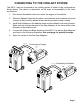
CONNECTING TO THE COOLANT SYSTEM The MCX-1 can be connected to the cooling system in either of the configurations shown below. The choice is dependent on the ease of accessability to the hose connections. 1. Disconnect the radiator hose from either the engine or the radiator. 2. Select an Adapter Hose with the same inner diameter as the radiator hose and connect at the point the radiator hose was disconnected using a clamp. 3.
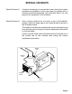
SPECIAL HOOKUPS Special Hookup 1) It may be necessary to reverse the hoses during the coolant replacement procedure on the next page for systems with a reverse-connected thermostat. See note after Step 6 on next page for the symptoms of this situation. Special Hookup 2) Some cooling systems do not have a cap on the radiator. Instead, there is a single cap on the overflow tank as shown in the illustration below.
COOLANT REPLACEMENT Once the MCX-1 is connected as described on the preceding pages it is ready to replace the old coolant with new coolant.
COMPLETING THE JOB All used coolant in the vehicle cooling system has now been replaced with new coolant. The following steps will complete the job.
COMPLETING THE JOB Green Hose Black Hose LOW & OVER RAD ERF IAT LOW OR EM PTY WA STE OFF TAN K FIL EXC L RADHAN GE IAT CO OR OLA & OVE NT RFL OR OW OFF LOW & EM PTY ER OVE RAD RFL IAT OW OR OFF WA STE TAN K EXC HAN GE FILL & OV RAD ERF IAT LOWOR COO LAN T Radiator Hose Engine Block Wand Heater Core Water Pump Radiator Overflow LO W & O ER R VE AD RF IAT LO O W R EM PT Y OF F WA ST E FIL EXC L R HA AD NG IAT E C OR OO & O LAN VE T O RF R LO W OF F EM PT YW LO W & O ER R VE AD RF IAT
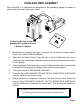
CHANGING COOLANT TYPE The MCX-1 has a means for easily using different types of coolants. A special feature is the clearing process which purges coolant from the hoses and pumps prior to changing the new coolant tank. The MCX-1 must be connected to a battery during this procedure.
CHANGING COOLANT TYPE Green Hose Black Hose LOW & ER OVE RAD RFL IAT OW OR EM PTY WA STE OFF TAN K FILLEXC HA RA NG DIA E TOR CO OLA & OVE NT RFL OR OW OFF LO W & O ER R VE AD RF IAT LO OR W LOW & EM PTY WA ER OVE RAD RFL IAT OW OR STE OFF TAN K EXC HAN GE & FIL L OV RAD ERF IAT LOWOR CO OLA NT EM PT Y OF F Green Hose WA ST E TA NK FIL EXC L R HA A D NG IAT E C OR OO & O LAN VE T O RF R LO W OF F Wand EM PT YW LO W & O ER R VE AD RF IAT LO OR W AS TE OF F TA NK EX CH AN GE F
EMPTYING THE WASTE TANK The Waste Tank can be emptied two different ways. A. The Waste Tank can be removed from the MCX-1 and transported to the area where it is to be emptied. A quick connect coupler is installed on the black hose to make this disconnection quick and clean. B. The MCX-1 can be used to pump the waste coolant directly from the Waste Tank into another waste collection tank. A 12 volt battery will be required to power the MCX-1.
REPLACEMENT PARTS Call 800-468-2321 (Extension 259) For Technical Support or Parts Ordering Visit our web-site at www.rtitech.
WASTE PUMP IMPELLER REPLACEMENT The waste pump impeller may require periodic replacement. The concentration of impurities in recovered old coolant affects the life of the pump impeller. Changing the impeller is quick and easy as follows: 1. Remove Hose Holder on rear of unit to access the end of the Waste Pump. 2. Remove 4 screws. 3. Remove cover plate, gasket and worn impeller. 4. Coat new impeller with Vaseline® petroleum jelly. 5. Align flats and press impeller onto shaft. 6.
FLOW & WIRING DIAGRAM Page 17