OPERATION MANUAL NTF-15 Nitrogen Tire Filling Valve Stem Caps (Qty=200) Order P/N 355-80026-00 RTI Technologies, Inc 10 Innovation Drive York, PA 17402 800-468-2321 www.rtitech.
Table of Contents Pictograms . . . . . . . . . . . . . . . . . . . . . . . . . . . . . . . . . . 1 Health, Safety and Environmental Aspects . . . . . . . . . . 1 Description of the NTF-15 Membrane . . . . . . . . . . . . . . 2 Process Parameters . . . . . . . . . . . . . . . . . . . . . . . . . . . 3 Unpack & Check Equipment . . . . . . . . . . . . . . . . . . . . . 3 Safety Precautions . . . . . . . . . . . . . . . . . . . . . . . . . . . . 4 Operation . . . . . . . . . . . . . . . . . . . . . . . . . . .
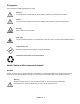
Pictograms In this manual the following pictograms are used: Warning A warning shows a hazard that can cause death or serious injury. Follow the instructions. Caution A caution shows a danger that can cause damage to the equipment. Follow the instructions. Warning Risk of death due to suffocation. Risk of fire Oxygen-enriched air leads to an increased risk of fire in the event of contact with flammable products. High pressure risk Follow the instructions with respect to compressed gasses.
Compressed air Warning Ensure that the feed air pressure can not exceed 190 psig. Nitrogen and Oxygen The NTF-15 generates nitrogen as a product. Oxygen enriched air is released as waste. Warning Nitrogen can cause suffocation! Oxygen-enriched air leads to increased risk of fire in the event of contact with flammable products. Make sure that there is adequate ventilation at all times! Do not install the NTF-15 in an area where explosive substances may be present.
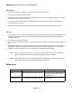
Ambient air contains nitrogen (78.1%), oxygen (20.9%), argon (1%), carbon dioxide, water vapor and traces of other inert gasses. Pressurized air (A) is fed through the hollow fiber membrane (B). The various air components diffuse through the wall of the membrane. The diffusion rate differs for the various gasses: Oxygen and water vapor have a high diffusion rate and permeate rapidly through the membrane wall. Nitrogen has a low diffusion rate and permeates slowly through the membrane wall.
Safety Precautions Warning Ensure there is sufficient ventilation. Only feed the NTF-15 with air. Keep the air feed to the NTF-15 clean and free of vapors of organic solvents and other contaminants. Do not place the NTF-15 in a room where organic solvent vapors may be present. Keep the ambient temperature between 40 and 110 /F. Do not connect hot compressed air directly from a compressor to the inlet of the NTF-15. Regular maintenance should be performed on the NTF-15 to ensure proper and safe operation.
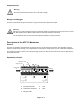
Operation (See Control Panel on Preceeding Page) Vacuum Tire 1. Connect shop air (120 - 150 PSI) to the air inlet port on the rear of the NTF-15. 2. Turn both panel valves to VACUUM TIRE. 3. Remove cap from tire valve stem. Place air chuck (on the end of the NTF-15 coiled green hose) on valve stem. Squeeze air chuck trigger to vacuum tire. 4. To check for vacuum, release trigger momentarily. If slide-out pressure gauge moves out, press trigger to continue the vacuum process. 5.
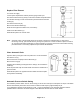
Replace Filter Element Turn off the air supply. Let the system depressurize until the pressure gauge reads 0 psi. Unscrew the bleed screw (F) slowly to ensure that the filter is depressurized. Turn the filter bowl (E) counter- clockwise and pull the bowl from the filter housing (A). Unscrew the blue knob (D). Remove the old filter element (C). Clean the sieve (B) and the filter house, if necessary. Install a new filter element (C). Assemble the parts in the reverse order.
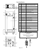
Parts Identification Part Number Description 1 026-80379-00 2" Gauge 0-160 psig/bar 1/4MPT 2 023-80364-00 FTG Test Port 1/4 MPT X valve stem 3 022-80028-00 3-way ball valve 1/4 FPT (BHD) 4 026-80330-00 pneumatic vacuum pump 5 022-80005-00 relief valve 300 psi 6 026-80380-00 nitrogen membrane (small) 7 022-80130-00 pneumatic pilot valve 8 022-80131-00 adjustable pneumatic pressure switch 9 022-80128-00 check valve 3/8 FPT 10 026-80377-00 15 gal vertical air tank 11 022-80129-
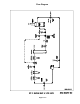
Flow Diagram Page 8 of 8