NTF-230 Operation Manual RTI Technologies, Inc. 10 Innovation Drive York, Pennsylvania 17402 USA Phone: 717-840-0678 Toll Free: 800-468-2321 Web-site: www.rtitech.
TABLE OF CONTENTS Pictograms 2 Health, Safety and Environmental Aspects......................
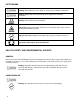
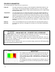
PICTOGRAMS Warning: Hazard that can cause death or serious injury. Follow the instructions. Caution: Danger that can cause damage to the equipment. Follow the instructions. Warning: Risk of death due to suffocation. Risk of fire: Oxygen-enriched air leads to an increased risk of fire in the event of contact with flammable products. High pressure risk: Follow the instructions with respect to compressed gasses. Instructions with respect to the environment.
NITROGEN AND OXYGEN The NTF-230 generates Nitrogen as a product. Oxygen enriched air is released as waste. Warning Nitrogen can cause suffocation. Oxygen enriched air leads to increased risk of fire in the event of contact with flammable products. Make sure that there is adequate ventilation at all times! Do not install the NTF-230 in an area where explosive substances may be present.
PROCESS PARAMETERS The nitrogen production depends on these parameters: Flow rate The lower the flow rate of compressed air through the hollow fiber membrane, the more oxygen can permeate through the membrane wall. As a result, the nitrogen produced at the outlet will have a higher purity. Nitrogen purity can be adjusted with the flow control valve. Temperature The NTF-230 operates at a temperature between 40-1100F (70-800F optimally).
UNPACK & CHECK EQUIPMENT Ensure that all components were delivered. Ensure that the compressed air source meets specification: Oil content of the compressed air is below 0.01mg/m3. Ensure that the compressed air pressure and quality is always as prescribed. Ensure that the air capacity is sufficient. CHARGE BATTERY FOR AT LEAST 5 HOURS PRIOR TO FIRST USE SAFETY PRECAUTIONS Warning Ensure there is sufficient ventilation. Only feed the NTF-230 with air.
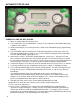
AUTOMATIC TIRE FILLING PURGE/FILL AND TOP OFF CYCLES 1. Attach air supply (150 PSI max) to the unit. 2. Turn control valve so it is HORIZONTAL. Verify pressure indicated on AIR PRESSURE gauge is between 120 - 150 PSI. 3. Allow unit to build pressure in nitrogen tank as shown on N2 PRESSURE gauge (approximately 120 PSI). 4. Turn on POWER switch on control panel. PCB will display battery charge status (HI or LO). Ensure that 12VDC battery is charged. See section on Battery charging for more information.
TOP OFF AND NITROGEN PURGE CYCLE COUNTER NTF-230 will total the number of Top Offs and Nitrogen Purge Cycles performed. 1. Press and hold + and - buttons simultaneously until unit beeps. 2. Press + or – button. 3. First displayed number shows thousands of Top Offs. 4. Press + or - button. Hundreds, tens and ones of Top Offs will be displayed. 5. Press + or - button. Thousands of Nitrogen Purge Cycles will be displayed. 6. Press + or - button.
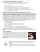
TESTING NITROGEN PURITY An optional item available for the NTF-230 is the NitroPRO Nitrogen Purity Tester. NitroPRO Nitrogen Purity Tester RTI P/N: 355 80022 00 The NitroPRO Nitrogen Purity Tester can be used to determine the percent of nitrogen produced by the NTF-230 by connecting to the Test Port (see picture below). It can also be used to determine the percent of nitrogen in the tires after performing a service. The NTF-230 is factory preset at 95% nitrogen purity and can be set as high as 98%.
MAINTENANCE Part Action Frequency Filter Element Replace Yearly or when indicator on the filter head moves to the CHANGE area as shown in the illustration to the right (change all 3 filters). Automatic Drain Clean When required ... IMPORTANT ... The condition of the Filter Element (mounted inside NTF-230) can only be checked when shop air is connected to the unit and it is in the FILL TIRE mode of operation with Nitrogen being generated and filling the tank.
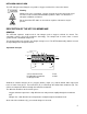
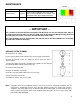
CLEAN AUTOMATIC DRAIN Turn the filter bowl (A) counter-clockwise one eighth of a turn and pull the filter bowl down from the filter housing. Unscrew the nut (F). Remove the drain unit (B-E) from the filter bowl (A). Remove the O-ring (E). Carefully pull the floating house (B) from the seat (D). Do not bend the needle (C). Clean the parts with soap and water. Make sure that the needle bore is open and clean. Assemble the parts in the opposite direction. Make sure that the parts are dry before reassembly.
ELECTRIC DIAGRAM FLOW DIAGRAM 11
PARTS IDENTIFICATION 16 15 9 8 6 7 Part Number 1 026 80452 00 Description 2 inch Gauge 0-160 psig/bar 1/4MPT 2 023 80364 00 FTG Test Port 1/4 MPT X valve stem 3 022 80579 00 30 gal vertical tank 4 026 80394 00 nitrogen membrane (2.