NTF-515 Operation Manual RTI Technologies, Inc. 10 Innovation Drive York, Pennsylvania 17402 USA Phone: 717-840-0678 Toll Free: 800-468-2321 Web-site: www.rtitech.
TABLE OF CONTENTS Pictograms 3 Health, Safety and Environmental Aspects......................
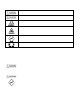
PICTOGRAMS Warning: Hazard that can cause death or serious injury. Follow the instructions. Caution: Danger that can cause damage to the equipment. Follow the instructions. Warning: Risk of death due to suffocation. Risk of fire: Oxygen-enriched air leads to an increased risk of fire in the event of contact with flammable products. High pressure risk: Follow the instructions with respect to compressed gasses. Instructions with respect to the environment.
NITROGEN AND OXYGEN The NTF-515 generates Nitrogen as a product. Oxygen enriched air is released as waste. Warning Nitrogen can cause suffocation. Oxygen enriched air leads to increased risk of fire in the event of contact with flammable products. Make sure that there is adequate ventilation at all times! Do not install the NTF-515 in an area where explosive substances may be present.
PROCESS PARAMETERS The nitrogen production depends on these parameters: Flow rate Temperature Membrane pressure External pressure The lower the flow rate of compressed air through the hollow fiber membrane, the more oxygen can permeate through the membrane wall. As a result, the nitrogen produced at the outlet will have a higher purity. Nitrogen purity can be adjusted with the flow control valve. The NTF-515 operates at a temperature between 40-1100F (70-800F optimally).
UNPACK & CHECK EQUIPMENT Ensure that all components were delivered. Ensure that the compressed air source meets specification: Oil content of the compressed air is below 0.01mg/m3. Ensure that the compressed air pressure and quality is always as prescribed. Ensure that the air capacity is sufficient. CHARGE BATTERY FOR AT LEAST 5 HOURS PRIOR TO FIRST USE. SAFETY PRECAUTIONS Warning Ensure there is sufficient ventilation. Only feed the NTF-515 with air.
OPERATION FOREIGN SUBSTANCES IN TIRES Tires which have been in service may contain foreign substances such as leak sealers. It is important that these substances are not pulled into the NitroPro unit during the vacuum procedure, resulting in possible performance issues and costly repairs not covered by RTI’s warranty. When servicing a vehicle, first check the valve stems and valve stem caps for any type of fluid or foreign substance. Install deflators and allow all four tires to deflate to zero pressure.
AUTOMATIC TIRE FILLING PURGE/FILL AND TOP OFF CYCLES 1. Attach air supply (150 PSI max) to the unit. Verify pressure indicated on panel mounted Air Pressure gauge is between 120 - 150 PSI. 2. Turn both valve knobs to FILL TIRE. 3. Allow unit to build pressure in Nitrogen storage tank as shown on N2 pressure gauge (120 PSI). 4. Turn on POWER switch on the top of control panel. PCB will display battery charge status (HI or LO). Ensure that 12VDC battery is charged.
TOP OFF AND PURGE/FILL CYCLE COUNTER NTF-515 will total the number of Top Offs and Purge/Fill cycles performed. 1. Press and hold + and - buttons simultaneously until unit beeps. 2. Press + or – button. 3. First displayed number shows thousands of Top Offs. 4. Press + or - button. Hundreds, tens and ones of Top Offs will be displayed. 5. Press + or - button. Thousands of Purge/Fill cycles will be displayed. 6. Press + or - button. Hundreds, tens and ones of Purge/Fill cycles will be displayed. 7.
MANUAL SINGLE TIRE VACUUM AND FILL VACUUM TIRE 1. Install deflators and check for foreign substances as explained earlier. 2. Connect shop air to the air inlet port on the rear of the NTF-515. Verify pressure indicated on panel mounted Air Pressure gauge is between 120 - 150 PSI. 3. Turn both panel valves to VACUUM TIRE. 4. Remove deflator and connect Digital Pressure Gauge (on the end of the NTF-515 coiled green hose) to the tire valve stem. Squeeze handle to vacuum the tire.
TESTING NITROGEN PURITY The NTF-515 Purity Tester can be used to determine the percent of nitrogen produced by the NTF-515 by connecting to the Test Port. It can also be used to determine the percent of nitrogen in the air in the tires after performing a service. Refer to the Operation Manual for the NTF-515 Purity Tester (035-81169-00) for further details.
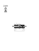
MAINTENANCE Indicator Action Frequency Filter Element Replace Yearly or when indicator on the filter head moves to the CHANGE area as shown in the illustration to the right. Automatic Drain Clean When required CLEAN CHANGE 560-80374-00 Part ... IMPORTANT ... The condition of the Filter Element (mounted on rear of unit) can only be checked when shop air is connected to the unit and it is in the FILL TIRE mode of operation with Nitrogen being generated and filling the tank.
CLEAN AUTOMATIC DRAIN Open the filter by turning the bowl one quarter turn counterclockwise. Unscrew the nut (F). Remove the drain unit (B-E) from the filter bowl (A). Remove the O-ring (E). Carefully pull the floating house (B) from the seat (D). Do not bend the needle (C). Clean the parts with soap and water. Make sure that the needle bore is open and clean. Assemble the parts in the opposite direction. Make sure that the parts are dry before reassembly.
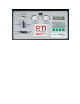
Part Number PARTS IDENTIFICATION 026-80379-00 2 inch Gauge 0-160 psig/bar 1/4MPT 2 023-80364-00 FTG Test Port 1/4 MPT X valve stem 3 022-80028-00 3-way ball valve 1/4 FPT (BHD) 4 026-80330-00 pneumatic vacuum pump 5 022-80149-00 pneumatic pilot valve 13 6 022-80131-00 adjustable pneumatic pressure switch 26 7 022-80128-00 check valve 3/8 FPT 8 022-80377-00 15 gal vertical tank 9 026-80395-00 nitrogen membrane (5.