OPERATION & MAINTENANCE MANUAL RHS730 Refrigerant Handling Station RTI Technologies, Inc. 4075 East Market Street P.O. Box 3099 York, Pennsylvania USA 17402 717-840-0678 (Ext. 259) Web: www.rtitech.com E-mail: tech@rtitech.
Two Modes of Operation The RHS730 can be used to perform semi-automatic procedures or run in a fully automatic mode. The following Table of Contents will direct you to the proper sections for detailed operating instructions. TABLE OF CONTENTS - RHS730 Before Using the RHS730 . . . . . . . . . . . . . . . . . . . . . . 2 Safety Precautions . . . . . . . . . . . . . . . . . . . . . . . . . . . . 2 How the RHS730 Operates . . . . . . . . . . . . . . . . . . . . . 3 Setup . . . . . . . . . . . . . . . . . . .
BEFORE USING THE RHS730 Check for any shipping damage. Place a claim with carrier if damage is discovered. DO NOT USE A DAMAGED UNIT. These general instructions describe normal operation and maintenance situations encountered with the RHS730. Failure to read and comply with these instructions or any one of the limitations noted herein can result in serious injury and/or property damage.
HOW THE RHS730 OPERATES The RHS730 is microprocessor controlled with a menu-driven user interface. All functions are performed by entering a few simple key strokes and following the prompts on the display. The on-board charge cylinder is mounted on a load cell. The weight of refrigerant in the charge cylinder is electronically displayed. The RHS730 has a Fill Cylinder feature which allows refrigerant to be transferred directly into the charge cylinder without going through the normal Recycle mode.
SETUP Anti-Blowback Valve New Refrigerant To Fill Port Page 4
WEIGHT= XX.X AUTOMATIC? 5 >>>> WEIGHT= FILL FILL CHARGE CYLINDER LB XX.X LB CYLINDER? 5 1. Connect a cylinder of new refrigerant to the Fill Port on the rear of the RHS730 as shown on Page 4. Anti-blowback Valve must connect to the RHS730. Turn the cylinder up-side-down. Turn Main Power Switch on. The display will show WEIGHT= XX.X LB AUTOMATIC? 5. > key four times to display WEIGHT= XX.X LB FILL 2. Press the CYLINDER? 5. 3. Press the ENTER key. The display will read START? 5. ENTER 4.
WEIGHT= XX.X RECYCLE LB AUTOMATIC? 5 1. See RHS730 Setup on Page 4. Turn Main Power Switch on. The display will show WEIGHT= XX.X LB AUTOMATIC? 5 > WEIGHT= XX.X LB RECYCLE? 5 ENTER RECYCLE HOLD TIME MIN XX > 3. Press the key one time to display WEIGHT= XX.X LB RECYCLE? 5 and press the ENTER key. The Display will read RECYCLE HOLD TIME XX MIN 5.
DRAIN RECOVERED OIL Oil is separated from the recycled refrigerant and MUST be removed following EACH Recycle procedure to determine the amount (if any) required to add into the A/C system as follows: 1. Turn Main Power Switch on. The display will show WEIGHT= XX.X LB AUTOMATIC? 5. 2. Press and hold the Oil Drain Re-pressurization Switch on the rear of the RHS730 for five seconds. 3. Slowly open the valve on the Oil Drain Bottle to drain any oil which may have been removed from the A/C System.
WEIGHT= XX.X AUTOMATIC? DEEP VACUUM LB 5 >> 1. See RHS730 Setup on Page 4. Turn Main Power Switch on. 2. Attach Red and Blue Hoses to the A/C System per the vehicle manufacturer's instructions. Open the Red and Blue Hose Valves. WEIGHT= XX.X VACUUM? LB 5 3. Press the > key two times to display WEIGHT= XX.X LB VACUUM? 5 and press the ENTER key. The Display will read ENTER VACUUM TIME XX MIN 5.
WEIGHT= XX.X CHARGE LB AUTOMATIC? 5 >>> 1. See RHS730 Setup on Page 4.Turn the Main Power Switch on. 2. Attach the Red and Blue Hoses to the A/C system per the vehicle manufacturer's instructions and open the Red and Blue Hose Valves. WEIGHT= XX.X LB CHARGE? 5 ENTER ENTER CHARGE AMOUNT= XX.X LB5 >< ENTER 3. Determine the refrigerant capacity of the A/C system to be charged. 1 oz = 0.02835 Kg 1 Lb = 0.45359 Kg 4. Press the > key three times to display WEIGHT= XX.
WEIGHT= XX.X AUTOMATIC? LB 5 RECYCLE HOLD TIME MIN XX 1 oz = 0.02835 Kg 5 >< ENTER ENTER TIME XX MIN PERFORM TEST? Y/N5 < ENTER OIL? Y/N5 < ENTER ENTER CHARGE AMOUNT= XX.X LB5 >< ENTER * LEVEL , FILL The Recycle Hold Time is the length of time that the RHS730 waits for out-gassing or for the pressure in the A/C system being recycled to rise enough to automatically restart the recycling process. The minimum value is two minutes.
WEIGHT= XX.X COMPRESSOR WEIGHT= * HIGH SEE ON XX.X COMPRESSOR LB OFF PRESSURE MANUAL ** CYLINDER GO TO FULL CHARGE AUTOMATIC - Continued LB 5 The Display will read WEIGHT= XX.X LB COMPRESSOR ON. The RHS730 will recycle refrigerant from the A/C system and automatically cycle off when a vacuum is sensed. This vacuum level can be seen on the Low Pressure Gauge. The Display will read WEIGHT= XX.X LB COMPRESSOR OFF. * This screen will display if there is an internal fault.
ENTER ADD AUTOMATIC - Continued OIL NOW 5 14. If Add Oil was selected by choosing Y in Step 8 the Display will read ADD OIL NOW CONTINUE? 5 and the Attention Light will turn on. (Skip to Step 15 if Add Oil was not selected). LB Fill the Oil Charge Bottle. Open the valve on the Oil Charge Bottle and leave it open until the correct amount of oil (measured in Step 12) has left the Oil Charge Bottle. Close the valve on the Oil Charge Bottle and press the ENTER key to continue.
WEIGHT= XX.X LB AUTOMATIC? 5 XX.X LB SETUP? 5 ENTER See Filter Maintenance (Page 15) for the procedure to change the filters. The normal Filter Change Interval is after every 25 hours. Press and hold the < key and press the RESET key to remove the CHANGE FILTERS 5 message. 3. Press the > key. The Display will read TOTAL RECYCLED XXXX.X KG. FILTER XX.X 1. Turn the Main Power Switch on. 2. Press the > key five times to display WEIGHT= XX.X LB SETUP? 5 and then press the ENTER key.
SET OVER CHARGE AMOUNT 1. Remove two screws on each side to remove front cover. Remove four screws and carefully tilt top control panel up to gain access to printed circuit board cover. WEIGHT= XX.X AUTOMATIC? LB 5 >>>>> ENTER WEIGHT= Refer to the figure below to locate the access hole for the Calibration Switch which is on the underside of the Circuit Board Cover. 3. Remove the plastic Calibration Tool. XX.X SETUP? LB 5 XX.X 4. Press the > key five times to display WEIGHT= XX.X LB SETUP? 5 . 5.
CALIBRATE WEIGHT SCALE WEIGHT= XX.X AUTOMATIC? LB XX.X SETUP? LB 5 Press Calibration Switch WEIGHT= Remove two screws on each side and remove front cover. Remove four screws and carefully tilt top control panel up to gain access to printed circuit board cover. Refer to the illustration on preceding page. 2. Remove Red Hose from High Side Port and connect the Blue Hose from the High Side Port to the Vapor Port of a DOT cylinder. Use Low Side Tank Adapter (RTI Part Number 023-80147-00).
SCHEDULED MAINTENANCE DAILY... Check the oil level in the Vacuum Pump while the pump is running. The Vacuum Pump Oil Level Sight Glass is visible through a hole in the Left Side Panel of the RHS730. The oil level should be at the “half-way” point of the glass. If oil is not visible call Technical Support at 800-468-2321 extension 259. MONTHLY... Clean the Condenser to maintain high efficiency performance of the RHS730. Disconnect power and remove the panel below the filters on the rear of the RHS730.
PARTS IDENTIFICATION - Front View P/N DESCRIPTION 1 024-80097-01 Circuit Board 120V 2 024-80040-00 Rocker Switch SPDT (on-on) Amber (125V) 3 026-80065-03 Gauge 30 InHg - 120 PSIG 1/4 MFL 3.5 in.
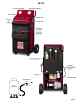
PARTS IDENTIFICATION - Rear View P/N DESCRIPTION 1 026-80069-00 Combo Filter 3/8 Flare (Short) 2 026-80208-00 Oil Charge Bottle with Valve 026-80208-01 Oil Charge Bottle only 3 026-80077-00 Combo Filter 3/8 Flare (Long) 4 024-80035-00 Rocker Switch SPST Momentary On - Non-lighted 5 026-80207-00 Oil Drain Bottle with Valve 026-80207-01 Oil Drain Bottle only 6 026-80229-00 Vacuum Pump - 7 CFM 10 360-81439-00 Condenser Assembly 11 360-80416-00 Fan Assembly 12 360-81670-01 Compre
Solenoid & Contactor Identification Page 19