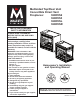
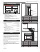
Multisided Top/Rear Vent Convertible Direct Vent Fireplaces: 360DVS2 360DVS3 360DVSL 360DVSR INSTALLER/CONSUMER SAFETY INFORMATION PLEASE READ THIS MANUAL BEFORE INSTALLING AND USING APPLIANCE IMPORTANT: Read all instructions and warnings carefully before starting installation. Failure to follow these instructions may result in a possible fire hazard, and will void the warranty.
360 DVS Series Direct Vent Fireplaces Table of Contents Thank you, and Congratulations on your purchase of a CFM Corporation Fireplace. PLEASE READ THE INSTALLATION & OPERATING INSTRUCTIONS BEFORE USING APPLIANCE. IMPORTANT: Read all instructions and warnings carefully before starting installation. Failure to follow these instructions fully may result in a possible fire hazard and will void the warranty. Installation and Operating Instructions ................................................................
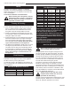
60DVS Series Direct Vent Fireplaces Installation & Operating Instructions This gas appliance should be installed by a qualified installer, preferably NFI or WETT (Canada) certified, in accordance with local building codes and current CSA-B149.1 Installation Codes for Gas Burning Appliances and Equipment. If the unit is being installed in a mobile home, the installation should comply with the current CAN/CSA Z 240.4 code. For U.S.A.
360 DVS Series Direct Vent Fireplaces Requirements for the Commonwealth of Massachusetts All gas fitting and installation of this heater shall only be done by a licensed gas fitter or licensed plumber.
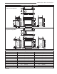
360DVS Series Direct Vent Fireplaces Fireplace Dimensions - 360DVS2 I Rear Vent Configuration J J K H H K B G E A E A D Electrical Access Electrical Access J J K Gas Line Access J Gas Line Access F C J Top Vent Configuration 6326 360DVS2 rear vent specs H J K J K H K B G C I E A E A D Electrical Access Electrical Access J K J F Fig. 1a Fireplace specifications—360DVS2 Ref.
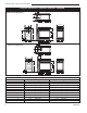
360 DVS Series Direct Vent Fireplaces Fireplace Dimensions - 360DVS3 / 306DVSL / 360DVSR K Rear Vent Configuration I J H H B K ROD A E G D Electrical Access J Gas Line Access J K C K Top Vent Configuration H I J C F B 6326 360DVS3 rear vent specs H K B G A E Electrical Access J K D Gas Line Access J B F C 6326 Fig. 1b Fireplace specifications—360DVS3/ 360DDVSL/ 360DVSR 360DVS3 top vent Ref.
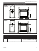
360DVS Series Direct Vent Fireplaces Framing Dimensions - 360DVS2 Rear Vent Configuration ROD ROH CFM121 ROW Top Vent Configuration ROD CFM121 360DVS2 REAR VENT CONFIGURATION 8/10/00 ROH ROW CFM122 Fig. 2a Fireplace framing dimensions—360DVS2 Ref. ROD ROH ROW 10006326 CFM122 360DVS2 - TOP VENT CONFIGURATION Framing Dimensions 8/10/00 Rear Vent Configuration Top Vent Configuration 24” (610 mm) minus two times finishing material thickness to be even with face of unit.
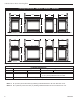
360 DVS Series Direct Vent Fireplaces Framing Dimensions - 360DVS3 / 360DVSL / 360DVSR Rear Vent Confiration ROD ROW ROH ROH 360DVSL ROD CFM123_360DVS3_dims_RV2 REAR VENT CONFIGURATION 8/10/00 rev. 8-23-02 rjs ROW 360DVSR ROD 360DVS/3/L/R CFM123 ROD ROH ROH ROH 360DVSL ROH 360DVS3 360DVS/3/L/R Top Vent Configuration ROD ROD 360DVS3 360DVSR CFM124 Fig. 2b Fireplace framing dimensions—360DVS3/ 360DVSL/ 360DVSR CFM124_360DVS3_TV2 TOP VENT CONFIGURATION Ref.
360DVS Series Direct Vent Fireplaces Locating Your Fireplace V W X Y X Z X X Y A B Z Y A Y A B C D E Fireplace Louvre Assembly Top LU584-2 Fig. 3 LocatingLU584-2 your gas fireplace A Wall Location (Fig. 3) 360DVS Y (Minimumlocate distancefireplace between a glass panel and a parallel wall) = 3’ (914mm) Z (Minimum distance between edge of a glass panel and an adjacent wall) = 3” (76mm) B Island Location (Fig. 3) X (Maximum length of horizontal venting) = 20’ (6.
360 DVS Series Direct Vent Fireplaces Hearth Gas Specifications A hearth is not mandatory; however, for aesthetic purposes, we recommend installing a noncombustible hearth that projects out 12” (305mm) or more from the front of the fireplace. Cold climate installation recommendation: When installing this unit against a noninsulated exterior wall or chase, it is mandatory the outer walls be insulated to conform to applicable insulation codes. Framing & Finishing 1. Choose the unit location. 2.
360DVS Series Direct Vent Fireplaces 1/2” Gas Supply 1/2” NPT X 1/2” Flare Shut-Off Valve 3/8” Flex Line (From Valve) 7. Refit the socket assembly back into the electrical box and replace the cover plate. 8. The EB-1 electrical junction box is now ready to supply power to the FK12 or FK24 fan kit, if used. FP297a Fig. 5 Gas shutoff valve and flex connector. Electrical Inlet Hole When using copper or flex connector, use only approved fittings.
360 DVS Series Direct Vent Fireplaces Remove These Screws Remove These Screws FP1430 Fig. 8 Alternate switch location. Optional Top Vent Application This appliance is shipped as a rear vent unit. If the installation layout requires the unit to be a top vent configuration, the appliance can be converted by following the steps below. Outer Collar Adapter FP1431 Fig. 9 Remove screws from outer collar adapter.
360DVS Series Direct Vent Fireplaces Electronic Gas Control Valve This appliance may be fitted with a Honeywell ignition module. Installation of the remote ON/OFF starter switch on electronic ignition units (Fig. 12): 1. Thread the wiring through the holes on the side panels of the appliance. Take care not to cut the wire or insulation on metal edges. Route the wire to a conveniently located receptacle box. 2. Attach the wire to the ON/OFF switch and install the switch into the receptacle box. 3.
360 DVS Series Direct Vent Fireplaces General Venting Information - Termination Location INSIDE CORNER DETAIL G V H A N N D L V E C B V F B ����� ������ Ope rable V B Operable B V Fixed Closed B V J X X AIR SUPPLY INLET M I A CFM145a V VENT TERMINATION B V C = Clearance to permanently closed window D = Vertical clearance to ventilated soffit located above the terminal within a horizontal distance of 2’ (610mm) from the center line of the terminal E = Clearance to unventilated s
360DVS Series Direct Vent Fireplaces Termination Clearances Termination clearances for buildings with combustible and noncombustible exteriors. Inside Corner Alcove Applications* Outside Corner G= Combustible 6" (152 mm) G F= Combustible 6" (152 mm) Noncombustible 2" (51 mm) V Noncombustible 2" (51 mm) V C V E O F Balcony with perpendicular side wall Balcony with no side wall D C E = Min. 6” (152 mm) for non-vinyl sidewalls Min. 12” (305 mm) for vinyl sidewalls O = 8’ (2.4 m) Min.
360 DVS Series Direct Vent Fireplaces How to Use the Vent Graph Rear Wall Application The vent chart should be read in conjunction with the following vent installation instructions to determine the relationship of the vertical and horizontal dimensions of the vent system. When installed as a rear vent unit this appliance may be vented directly to a termination located on the rear wall behind the appliance. 1. Determine the height of the center of the horizontal vent pipe exiting through the outer wall.
360DVS Series Direct Vent Fireplaces STEP 5 Vent Opening for Combustible Wall Guide vent through the vent hole as you place the appliance in its installed position. Guide the 4” (102 mm) and 7” (178 mm) collars of the vent termination into the outer ends of the venting. 9³⁄₈” (240mm) Do not force the termination. If the vent pipes do not align with the termination, remove and realign the venting at the appliance flue collars.
360 DVS Series Direct Vent Fireplaces Horizontal plane means no vertical rise exists on this portion of the vent assembly. • The maximum number of 90˚ elbows per side wall installation is three (3). • If a 90˚ elbow is fitted directly on top of the fireplace flange, the maximum horizontal vent run before the termination or a vertical rise is 36” (914mm). Max. 20” (508mm) Max. 36” (914mm) • The maximum number of 45° elbows permitted per side wall installation is two (2).
360DVS Series Direct Vent Fireplaces STEP 4 Vent Opening for Combustible Wall Apply a bead of silicone to the inner and outer flue collars of the fireplace and using appropriate length of pipe section(s) attach to fireplace with three (3) screws. Follow with the installation of the inner and outer elbow, again secure joints as described in “Connecting Vent Pipes” section.
360 DVS Series Direct Vent Fireplaces 2” (51 mm). Secure termination to the wall with screws provided, and caulk around the wall plate to weatherproof. Zero Clearance Sleeve (if required) One alternative to screwing the termination directly to the wallis the use of expanding plugs or an approved exterior construction adhesive.
360DVS Series Direct Vent Fireplaces Vertical Through-the-Roof Application This Gas Fireplace has been approved for: 1 + 2 + 3 + 4 = 270° • Vertical installations up to 40’ (12 m) in height. Up to a 10’ (3 m) horizontal vent run can be installed within the vent system using a maximum of two 90° elbows. (Fig. 30) 1 2 3 4 Max. Height 40’ (12.2m) Min. Height 8’ (2.4m) 1 2 3 4 Max. 10’ (3m) FP1444 Fig. 31 Maximum elbow usage. Support Straps Every 36” (914mm) Min. 2' (610 mm) Max. 10’ (3m) Max.
360 DVS Series Direct Vent Fireplaces Vertical Through-the-Roof Installation 1. Locate your fireplace. 2. Plumb to center of the (4”) flue collar from ceiling above and mark position. 3. Cut an opening equal to 9³⁄₈” x 9³⁄₈” (240 x 240mm). 4. Proceed to plumb for additional openings through the roof. In all cases, the opening must provide a minimum of 1” (25 mm) clearance to the vent pipe, i.e., the hole must be at least 9³⁄₈” x 9³⁄₈” (240 x 240mm). 5. Place fireplace into position. 6.
360DVS Series Direct Vent Fireplaces Twist Lock Venting Components 7TDVRVT Through-the-Wall Rear Vent Termination 584A venting components rear vent term 4/6/99 djt Starter Kit Model 7TDVSK - Sidewall Starter Kit Model 7TDVSKV - Vertical Venting for 7TDVSKV-A: order 1/12 to 6/12 roof pitch for 7TDVSKV-B: order 7/12 to 12/12 roof pitch for 7TDVSKV-F: order flat roof Starter Kit Model 7TDVSKS - Snorkel Kit Snorkel Termination - 7TDVSNORK for Below Grade Installation 45˚ Elbow 7TDVT45 for Rear Vent to Vertical
360 DVS Series Direct Vent Fireplaces Operating Instructions Glass Information Only glass approved by CFM Corporation should be used on this fireplace. • The use of any non-approved replacement glass will void all product warranties. • Care must be taken to avoid breakage of the glass. • Do not operate appliance with glass front removed, cracked or broken.
360DVS Series Direct Vent Fireplaces Glass Cleaning It is necessary to periodically clean glass. During startup, condensation, which is normal, forms on the inside of the glass. This condensation causes lint, dust and other airborne particles to cling to glass surface. Also initial paint curing may deposit a slight film on the glass. It is therefore recommended glass be cleaned two or three times with a non-ammonia based household cleaner and warm water.
360 DVS Series Direct Vent Fireplaces Side of Fireplace B120 B123 B125 B122 B126 B124 B121 LG320 Fig. 40 360DVS log placement. Side of Fireplace B123 B120 LG320 360DVS logs Venting Side Venting Side B121 B122 B126 B125 LG321 Fig. 41 360DVS log placement. Your log set contains Ember Material and two types of Lava Rocks. Set these materials in place after the logs have been installed. Ember Material (Pt.
360DVS Series Direct Vent Fireplaces HI Turn counterclockwise to increase flame height LO Turn clockwise to decrease flame height 3/8” - 1/2” (10 - 13mm) Fig. 43 Flame adjustment knob for SIT valve. Flame Characteristics FP390 F584-703 Fig. 45 Correct pilot flame appearance. It is important to periodically performKNOB a visual check FLAME ADJUSTMENT 11/21/96 of the pilot and burner flames. Compare them to the pictorials illustrated below. (Figs.
360 DVS Series Direct Vent Fireplaces Lighting and Operating Instructions FOR YOUR SAFETY, READ BEFORE LIGHTING. WARNING: If you do not follow these instructions exactly, a fire or explosion may result, causing property damage, personal injury or loss of life. A. This heater has a pilot light, which must be lit manually. When lighting the pilot follow these instructions exactly: B. BEFORE LIGHTING, smell all around the heater area for gas.
360DVS Series Direct Vent Fireplaces Lighting and Operating Instructions For Fireplaces equipped with SIT822 Gas Valve (EN or EP) Warning: If you do not follow these instructions exactly, a fire or explosion may result causing property damage, personal injury and loss of life. For your safety, read the following warnings before lighting the appliance: A. This fireplace is equipped with an ignition device which automatically lights the pilot. DO NOT try to light the pilot by hand. B.
360 DVS Series Direct Vent Fireplaces Troubleshooting the Gas Control System SIT NOVA 820 MILLIVOLT VALVE NOTE: Before troubleshooting the gas control system, be sure external gas shut off is in the “On” position. WARNING: REMOVE GLASS FRONT BEFORE DOING ANY GAS CONTROL SERVICE WORK. SYMPTOM 1. Spark ignitor will not light POSSIBLE CAUSES A. Defective or misaligned electrode at pilot. B. Defective ignitor (Push Button) 2. Pilot will not stay lit after A.
360DVS Series Direct Vent Fireplaces Troubleshooting the Gas Control System SIT 822 Valve with a Honeywell Electronic Igniter NOTE: Remove glass before servicing. START TURN GAS SUPPLY OFF. NO TURN ON/OFF SWITCH TO CALL FOR HEAT. CHECK: POWER TO MODULE? (24V NORMAL) YES SPARK ACROSS IGNITOR SENSOR GAP? NO LINE VOLTAGE (120VAC). LOW VOLTAGE TRANSFORMER (19.5 MINIMUM VAC). ON/OFF SWITCH. WIRING CONNECTIONS. UNPLUG IGNITION LEAD AND CHECK SPARK AT MODULE (24VAC NORMAL).
360 DVS Series Direct Vent Fireplaces Troubleshooting – Honeywell VS8421 START CHECK Gas Supply On NO • Supply Line Hooked Up • Shutoff Valve Open YES • Lockout Has Engaged. Wait 60 Pilot Lights With Piezo Ignitor • NO • • YES PILOT STAYS LIT Seconds And Try Again. For Spark At Electrode While Depressing Piezo 1/8" Gap To Pilot Hood Needed. All Wiring Connections Replace Piezo Ignitor • For Air In The Lines • Thermopile Needs A Min. NO • • • 325mv. Adjust Pilot Flame Height.
360DVS Series Direct Vent Fireplaces Fuel Conversion Instructions To convert this appliance from gas type to another, follow these instructions. Before proceeding, turn control knob to “OFF” and turn gas supply OFF. Turn OFF any electricity that may be going to the appliance. CAUTION: Logs may be HOT! Allow to cool before proceeding. This conversion procedure must be carried out by an authorized service provider. 1. Disconnect power to unit and shut off the gas supply. 2.
360 DVS Series Direct Vent Fireplaces E Regulator Cap Conversion Screw O HI L Pressure Regulator Housing OT N IL FP OF O D F HV120 FC108 Fig. 49 Replace regulator. Honeywell Gas Control FC108Valve (Fig. 50) The Honeywell valve SITfitted to this unit is suitable for use with LP or Naturalregulator Gas. It is converted to the required gas application by installing a color-coded conversion conversion screw.
360DVS Series Direct Vent Fireplaces Maintenance Burner and Burner Compartment It is important to keep the burner and the burner compartment clean. At least once per year remove the logs and lava rock/ember material. Vacuum and wipe out the burner compartment. Remove and refit the logs per the instructions in this manual. Always handle the logs with care as they are fragile and may also be hot if the fireplace has been in use. FK24/FK12 Fan Assembly The fan unit requires periodic cleaning.
0 DVS Series Direct Vent Fireplaces 1 1g 1f 1c 1a 8 1b 1e 1d 3a/b 2 11 9 14 O H 7 4a/b OFF 12 PILOT ADJ L ON P IL O I 10 6 16a/b T 13 5a/b 11 15a/b 20 22 24 25 26 29 27 19 28 23 18 21 17 31a/b 36 30 35 34a/b 37 25 LO 32 HI 33 CFM Corporation reserves the right to make changes in design, materials, specifications, prices and discontinue colors and products at any time, 6326 without notice.
360DVS Series Direct Vent Fireplaces 360DVS Series Ref. 1. 1a. 1b. 1c. 1d. 1e. 1f. 1g. 2. 3a. 3b. * * * 4a. 4b. 5a. 5b. 6. 7. 8. * * * * * * * 9. 10. 11. 12. 13. 14. 15a. 15b. 16a. 16b. 17. 18. * * * * 19. * * 20.
360 DVS Series Direct Vent Fireplaces 360DVS Series (continued) Ref. 21. 22. 23. 24. 25. 26. * * * * * 27. 28. 29. 30. * * * * * * * * * * * * 31a. 31b. 32. 33. 34a. 34b. 35. 36. 37.
360DVS Series Direct Vent Fireplaces Optional Accessories Fan Kits FK24 Fan Assembly This auxiliary fan system increases the efficiency of the circulation of the heated air. The FK24 fan kit allows variable speed control of the circulation fan and also incorporates a heat sensor in the circuit. Specifications 115 Volt / 60Hz / 56 Watts Maintenance The fan itself does not require regular maintenance, however periodic cleaning of the fan and the surrounding area is required.
360 DVS Series Direct Vent Fireplaces Wiring Instructions Decorative Trim Frame Kit The fireplace, when installed, must be electrically connected and grounded in accordance with local codes, or in the absence of local codes, with the current CSA C22.1 Canadian Electric Code. For USA installations, follow local codes and the National Electrical Code ANSI/ NFPA No. 70. Any electrical rewiring of this fan must be done by a licensed electrician.
360DVS Series Direct Vent Fireplaces 10006326 41
360 DVS Series Direct Vent Fireplaces 42 10006326
360DVS Series Direct Vent Fireplaces LIMITED LIFETIME WARRANTY PRODUCT COVERED BY THIS WARRANTY All Vermont Castings gas stoves, gas inserts, and gas fireplaces, and all Majestic brand gas fireplaces equipped with an Insta-Flame Ceramic Burner, or standard steel tube burner.
Efficiency Ratings Model 360DVS2RN 360DVS2RP 360DVS2EN 360DVS2EP 360DVS3RN 360DVS3RP 360DVS3EN 360DVS3EP 360DVSLRN 306DVSLRP 360DVSLEN 360DVSLEP 360DVSRRN 360DVSRRP 360DVSREN 360DVSREP EnerGuide Ratings Fireplace Efficiency (%) 62.4 62.4 62.4 62.4 62.4 62.4 62.4 62.4 62.4 62.4 62.4 62.4 62.4 62.4 62.4 62.4 Steady State (%) Fan-OFF Fan-ON 83 84 83 84 83 84 83 84 83 84 83 84 83 84 83 84 83 84 83 84 83 84 83 84 83 84 83 84 83 84 83 84 CFM Corporation 2695 Meadowvale Blvd.