
Installation Instructions


13
65D1009
EYF Series Unvented Gas Log Set
WARNING
FP2112
wiring diagram
12/08
Wall
Switch
On/Off Switch
On/Off
Switch
Millivolt
Valve
ODS Pilot
TH = 3
TP = 1
TP/TH =
ODS Pilot
Spade Terminal
Switch
Optional Wall
Switch or Remote
Receiver
FP11
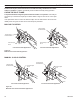
Figure 16 -
Wiring Diagram
1. Use 18 AWG, two-wire cable, 0 feet maximum length.
. At one end of the cable, connect both wires to the wall switch or thermostat. At the other
end, connect one wire to TP/TH and one wire to TH. The color of the wires does not matter.
Or you can hook the wall switch or thermostat to wires on the unit.