
Installation Manual


41
Hearth & Home Technologies • LCOR-DV36IN, RCOR-DV36IN Installation Manual • 2486-980 Rev. F • 7/18
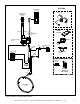
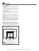
Install Vertical Termination Cap
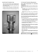
• Attach the vertical termination cap by sliding the inner
collar of the cap into the inner ue of the pipe section
while placing the outer collar of the cap over the outer
ue of the pipe section.
• Secure the cap by driving three self-tapping screws
(supplied) through the pilot holes in the outer collar of
the cap into the outer ue of the pipe (see Figure 7.15).
Important Notice: Heat shields may not be eld constructed.
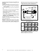
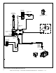
G. Horizontal Termination Requirements
Heat Shield Requirements for Horizontal
Termination
WARNING! Risk of Fire! To prevent overheating and re,
heat shields must extend through the entire wall thick-
ness.
• DO NOT remove the heat shields attached to the
wall shield restop and the horizontal termination cap
(shown in Figure 7.16).
• Heat shields must overlap 1-1/2 in. (38 mm) mini-
mum.
There are two sections of the heat shield. One section
is factory-attached to the wall shield restop. The other
section is factory-attached to the cap. See Figure 7.16.
If the wall thickness does not allow the required 1-1/2 in.
(38 mm) heat shield overlap when installed, an extended
heat shield must be used.
• If the wall thickness is less than 4 in./102 mm (DVP)
or 4-3/8 in./ 111 mm (SLP), the heat shields on the cap
and wall shield restop must be trimmed. A minimum
1-1/2 in. (38 mm) overlap MUST be maintained.
• Use an extended heat shield if the nished wall thickness
is greater than 7-1/4 in. (184 mm).
• The extended heat shield may need to be cut to length
maintaining suf cient length for a 1-1/2 in. (38 mm)
overlap between heat shields.
• Attach the extended heat shield to either of the existing
heat shields using the screws supplied with the extended
heat shield. Refer to vent components diagrams in the
back of this manual.
• Rest the small leg on the extended heat shield on top
of the pipe section to properly space it from the pipe
section.
Figure 7.15