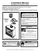
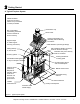
Installation Manual Installation and Fireplace Setup INSTALLER: Leave this manual with party responsible for use and operation. OWNER: Retain this manual for future reference. This fireplace uses SL300 Series Chimney 2” CLEARANCE TO COMBUSTIBLES AND BUILDING INSULATION FROM CHIMNEY REQUIRED. NOTICE: DO NOT discard this manual! Model(s): SA36C SA42C WARNING: If the information in these instructions is not followed exactly, a fire or explosion may result causing property damage, personal injury, or death.
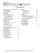
Safety Alert Key: DANGER! Indicates a hazardous situation which, if not avoided will result in death or serious injury. WARNING! Indicates a hazardous situation which, if not avoided could result in death or serious injury. CAUTION! Indicates a hazardous situation which, if not avoided, could result in minor or moderate injury. NOTICE: Indicates practices which may cause damage to the fireplace or to property. • • • • Table of Contents 1 Product Specific & Important Safety Information A. B. C. D.
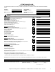
ATTENTION INSTALLER: Follow this Standard Work Checklist This standard work checklist is to be used by the installer in conjunction with, not instead of, the instructions contained inhis t installation manual. Customer: Lot/Address Model (circle one): SA36C SA42C Date Installed: Location of Fireplace: Installer: Dealer/Distributor Phone # Serial #: WARNING! Risk of Fire or Explosion! Failure to install fireplace acording to these instructions can lead to a fire or explosion.
1 Product Specific & Important Safety Information A. Fireplace Certification B. Non-Combustible Materials This fireplace may be installed in sleeping rooms. This fireplace is not approved for installation in manufactured homes. If installed with a gas log set, provisions for the National Fuel Gas Code must be met. • This fireplace system has been tested and listed in accordance with UL 127 and ULC-S610 standards by Underwriters Laboratories Inc.
2 Getting Started A.
B. Design and Installation Considerations Consideration should be given to these factors before deciding on a location. NOTICE: Check building codes prior to installation. • Installation MUST comply with local, regional, state and national codes and regulations. Consult insurance carrier, local building inspector, fire officials or authorities having jurisdiction over restrictions, installation inspection and permits. Before installing, determine the following: - Where the fireplace is to be installed.
2. Locating Fireplace & Chimney Location of the fireplace and chimney will affect performance. • • • • • • • Install within the warm airspace enclosed by the building envelope. This helps to produce more draft, especially during lighting and die-down of the fire. Installing the fireplace in a basement is not recommended. Penetrate the highest part of the roof. This minimizes the effects of wind loading. Locate termination cap away from trees, adjacent structures, uneven roof lines and other obstructions.
C. Tools and Supplies Needed E. Fireplace System Requirements Before beginning the installation be sure the following tools and building supplies are available: The HHT fireplace system requirements consist of the following: Reciprocating saw Framing material • Pliers Non-combustible sealant Hammer Gloves Phillips screwdriver Framing square Flat blade screwdriver Electric drill and bits Plumb line Safety glasses Level Tape measure • • 1/2-3/4 in.
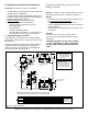
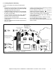
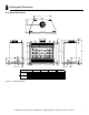
3 Framing and Clearances A. Fireplace Dimensions C D 8-3/4 [221] 22-3/4 [578] B 10-1/2 [267] 3-1/2 [88] 1-1/2 [39] 6-1/4 [158] 23-3/8 [594] 9-5/8 [245] 9-1/4 [235] 4-1/4 [108] 8-5/8 [220] 13-1/2 [341] 37-3/4 [958] 9-1/4 [235] 8-1/8 [207] Model # SA42 Figure 3.1 in. mm in.
B. Clearances Minimum Clearances to Combustibles WARNING! Risk of Fire! WITHIN ENCLOSURE AREA You must comply with all minimum air space clearances to combustibles as specified in Figure 3.2. DO NOT pack required air spaces with insulation or other materials. Framing or finishing material used on the front of, or in front of, the fireplace closer than the minimums listed must be constructed entirely of non-combustible materials (i.e., steel studs, concrete board, etc.). Failure to comply may cause fire.
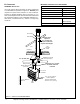
C. Construct the Chase Round Termination Cap A chase is a vertical boxlike structure built to enclose the fireplace and/or its vent system. Vertical chimneys that run on the outside of a building must be installed inside a chase. Storm Collar Metal Chase Top Ceiling Firestop In cold climates, Hearth & Home Technologies recommends that the chase be well insulated using batt type insulation between the joists. Construction of the chase may vary with the type of building.
D. Frame the Fireplace The finished cavity depth must be no less than 23 in. (584 mm) from the finished backwall to the outside of front wall framing. NOTICE: Hearth extension design must be determined before installation of fireplace. If the fireplace is placed on the floor the maximum height of a finished raised hearth is 2 in. (51 mm), if you want a higher raised hearth the fireplace must be placed on a platform. CAUTION! Risk of Cuts/Abrasions.
F. Protective Metal Hearth Strips WARNING! Risk of Fire! Protective metal hearth strips MUST be installed on combustible surfaces. DO NOT cover metal strips with combustible materials. Sparks or embers may ignite flooring. WARNING! Risk of fire! High temperatures, sparks, embers or other burning material falling from the fireplace may ignite flooring or concealed combustible surfaces. • Protective metal hearth strips MUST be installed. • Hearth extensions MUST be installed exactly as specified.
G. Outside Air Kit (optional) If you install an outside air kit, Hearth & Home Technologies recommends you utilize the shortest duct run to optimize the performance of the outside air kit. The outside air inlet hood should be positioned in a manner that will not allow snow, leaves, etc. to block the inlet. In some installations the air duct may need to be run vertically.
4 Chimney and Termination Requirements A. Chimney Requirements Vertical distances are measured from the base of the fireplace as shown in Figure 4.1. Table 4.1 Chimney Requirements Minimum overall straight height 16.5 ft 5.03 m Minimum height with single offset/ return 16.5 ft 45.03 m Double offset/return minimum height 20 ft 6.1 m Maximum height 90 ft 27.43 m Maximum chimney length between an offset and return 20 ft 6.1 m Maximum distance between chimney stabilizers 35 ft 10.
B. Offsets/Returns • • Use an offset/return to bypass overhead obstructions. An offset and return can be used as a single entity or separated by chimney section(s). WARNING! Risk of Fire! DO NOT use offset/returns greater than 30°. Chimney draft will be restricted and could cause overheating and fire. Secure offsets with screws ( not to exceed 1/2” / 13 mm in length) Secure returns with strapping. Straight chimney sections may be secured with screws. Keep chimney sections from separating or twisting.
C. Termination Requirements • Install a cap approved and listed for this fireplace system. Locate cap where it will not become plugged by snow or other materials. Locate cap away from trees or other structures. The bottom of the termination cap must be at least 3 ft (.91 m) above the roof AND at least 2 ft (.61 m) above any portion of roof within 10 ft (3.05 m). The distance required between caps is shown below. Slanted Roofs Chimney must extend 2 ft (.
5 Chimney Installation A. Typical Chimney System NOTICE: Chimney performance may vary. • • Trees, buildings, roof lines and wind conditions affect performance. Chimney height may need adjustment if smoking or overdraft occurs.
B. Assemble Chimney Sections Use only those components described in this manual. Substitute or damaged chimney components could impair safe operation and cause overheating and fire. Attach either a straight chimney section or an offset to the top of the fireplace (depending on your installation requirement). Chimney sections are locked together by pushing downward until the top section meets the stop bead on the lower section. The inner flue is placed to the inside of the flue section below it.
C. Secure Offset/Return When offsets and returns are joined to straight pipe sections, they must be locked into position with the screws (outer only). To prevent gravity from pulling the chimney sections apart, the returns and the chimney stabilizers have hanger straps for securing these parts to joists or rafters. See Figure 5.3. * Use # 6 or # 8 sheet metal screw, or larger, no longer than 1/2 in. (13 mm). ROOM ABOVE (non-insulated ceiling) B Ceilng firestop attached to bottom of framing 2 in.
►E. Install Attic Insulation Shield WARNING! Risk of Fire! You MUST install an attic insulation shield when there is any possibility of insulation or other combustible material coming into contact with the chimney. • • • Pre-bend the tabs to rest against pipe to prevent insulation from falling in. DO NOT pack insulation between the chimney and the attic insulation shield. Failure to keep insulation and other materials away from chimney pipe could cause fire. DO NOT offset chimney inside insulation shield.
F. Roof Penetration • • • • Refer to Figure 5.8. Plumb from roof to center of chimney. Drive a nail up through roof to mark center of pipe. Measure to either side of nail and mark the 14-1/2 in. x 14-1/2 in. (368 mm x 368 mm) opening required. Measure opening on the horizontal; actual length may be larger depending on roof pitch. Cut out and frame opening. • • Install Flashing • • Assemble chimney so it passes through the framed opening. Slip the flashing over the chimney.
H. Termination Cap Requirements • • • • Install a cap approved and listed for this fireplace system. Locate cap where it will not become plugged by snow or other materials. Locate cap away from trees or other structures. The bottom of the termination cap must be at least 3 ft (.91 m) above the roof AND at least 2 ft (.61 m) above any portion of roof within 10 ft (3.05 m). I. Install Termination Cap Install the chimney sections up through the chase enclosure.
Termination Cap Place waterproof sealer under each flange of the termination cap and on top of each screw to help prevent leaks. The last section of pipe must stop between 2 in. (51 mm) above the top of the chase and 4 3/4 in. (121 mm) below the top of the chase. Collar 2 in. (51 mm) Minimum Height Chase Top Remove 2 screws from front & back to lift the top off Termination Cap Place waterproof sealer under each flange of the termination cap and on top of each screw to help prevent leaks.
6 Shrouds WARNING! Risk of Fire! Shrouds must be constructed as specified. Improper construction may overheat chase top. Shrouds may be field constructed where permitted by regional building codes. 1. Open Top Shroud TR342/344 TV (top vented) caps do not require radiation shield. NOTICE: Some regional codes require an agency-Listed shroud. Consult your local building officials. Min. Top Dim. Min. Top Dim. The shrouds must be constructed from minimum .018 in. (26 ga) thick aluminized steel.
2. Mailbox Style Shroud Radiation shield required Minimum Opening Height 3 in. (76 mm) Min. Opening Height Min. Height above bottom of termination cap Radiation Shield TR344 TR342-B Min. Base Dims. Min, Base Dim Min. Base Dim TR342-B TR344/ with TR-TVK in 26-1/2 x 28 28 x 30 mm 673 x 711 711 x 762 Min. Height Above Bottom of Termination Cap Min, Opening Width 3 in. (76 mm) Min. Radiation Shield Height from top of Chase in 28-1/4 27-1/2 718 698 mm Min.
7 Finishing A. Finishing Material Refer to Sections 1.B. and Sections 1.C. for combustible/ non-combustible materials. Refer to Figure 7.1 for noncombustible zone. These surfaces may be covered with non-combustible material. WARNING! Risk of Fire! You must maintain clearances. • • • • • • High temperature sealant. Do NOT cover metal fireplace front with combustible materials. Install combustible materials only to specified clearances on top front and side edges.
B. Hearth Extension, Building and Finishing WARNING! Risk of Fire! • Maintain clearances. • Use only non-combustible material below standoffs, material such as cement board is acceptable. • Framing or finishing material used on the front of the fireplace closer than the minimums listed, must be constructed entirely of non-combustible materials (i.e., steel studs, concrete board, etc.).
1. Fireplace Installed Flush on the Floor and Hearth Extension Raised to Bottom of Firebox Opening Non-combustible flooring a minimum of 16 in. (406 mm) in front of and 8 in. (203 mm) to each side of fireplace opening of the SA36R. 20 in. (508 mm) in front and 12 in. (305 mm) to each side of the SA42R is required. The hearth framing must be constructed of non-combustible materials (such as metal framing or equivalent material) and placed on HX3(s), HX4(s), or equivalent material. See Figures 7.4 and 7.5.
2. Raised Hearth Extension and Raised Fireplace Non-combustible flooring a minimum of 16 in. (406 mm) in front of and 8 in. (203 mm) to each side of fireplace opening of the SA36R. 20 in. (508 mm) in front and 12 in. (305 mm) to each side of the SA42R is required. The hearth framing must be constructed of non-combustible materials (such as metal framing or equivalent material) and placed on HX3(s), HX4(s), or equivalent material. See Figure 7.8.
C. Non-Combustible Sealant Material After completing the installation of non-combustible material in the required non-combustible zone and the non-combustible finishing material over that, a bead of non-combustible sealant must be used to close off any gaps at the top and sides between the fireplace and hearth. Non-combustible Sealant Figure 7.
D. Mantel and Wall Projections The combustible mantel may have a maximum depth of 12 in. (305 mm), positioned 12 in. (305 mm) above the fireplace opening. Combustible trim pieces that project no more than 1-1/2 in. (38 mm) from the face of the fireplace can be placed no closer than 6 in. (152 mm) from the top of the fireplace opening.
E. Sidewalls/Surrounds Grid represents 1 in. scale FLUSH FRONT 4 in. [102 mm] Model # SA36 le SA42 A ng 10 3/4 in. [273 mm] BRICK FRONT 39 °a °a • Locate adjacent combustible sidewalls a minimum of 12 in. (305 mm) from fireplace opening. Mantle leg, surround, stub wall, whether combustible or non-combustible, may be constructed as shown in Figure 7.13. 50 • ng le in. mm in. mm A Fireplace Opening B Outside Dimensions 36 914 42 1067 42 1067 48 1219 9 3/4 in. [248 mm] B 12 in.
8 Fireplace Setup A. Gas Log/Lighter Provision WARNING! Fire and/or Asphyxiation Risk! Use with solid wood fuel or decorative gas appliance only. Gas fire generates fumes. A certified gas log lighter or decorative gas log set can be installed in this fireplace. Firebox • • • • • • CAUTION! If an unvented gas appliance is installed in the fireplace, the gas appliance must only be operated with the fireplace glass door fully open (if included).
9 Reference Materials A. Chimney Components Catalog # Description CAK4A Chimney Air Kit ID4/ID6 Insulated Duct/Outside Air UD4/UD6 Uninsulated Duct/Outside Air SL306 Chimney Section - 6 in. (152 mm) long SL312 Chimney Section - 12 in. (305 mm) long SL318 Chimney Section - 18 in. (457 mm) long SL324 Chimney Section - 24 in. (610 mm) long SL336 Chimney Section - 36 in. (914 mm) long SL348 Chimney Section - 48 in.
A Inside Diameter 8 in. (203 mm) Outside Diameter 10-1/2 in. (267 mm) Effective Height 4-3/4 in. (121 mm) SL315/SL330 Offset/Return B 14-1/2 in. (368 mm) Ceiling Firestop Catalog # A FS338 0-deg. 14-1/2 in. B 368 mm FS339 15-deg. 18-3/8 in. 467 mm FS340 30-deg. 23 in. 584 mm 12 in. (305 mm) AS8 Straight Attic Insulation Shield 10-1/2 in. (267 mm) 2 in. (51 mm) JB877 Chimney Joint Band 10-1/2 in. (267 mm) CB876 Chimney Joint Band 24-5/8 in. (625 mm) 27-3/8 in.
15-3/4 in.
20 in. (508 mm) 21 3/16 in. (538 mm) 34 in. (864 mm) 34 in. (864 mm) 24 in. (610 mm) 24 in. (610 mm) DTO134 DTS134 22 3/4 in. (577 mm) 21 3/16 in. (538 mm) 46 in. (1168 mm) 38 46 in. (1168 mm) 26 in. (660 mm) 26 in.
B. Optional Components 52 in. (1321 mm) 16 in. (406 mm) C D B 1/2 in. (13 mm) A LDS33/LDS46 Decorative Shroud HX3 Hearth Extension A 66 in. (1676 mm) Catalog # 20 in. (508 mm) in. B mm in. C mm in. D mm in. mm LDS33 36 914 36 914 8.5 216 11 279 LDS46 48 1219 72 1829 8.5 216 11 279 LDSCPM - Corner Post Kit (for custom sizes) 1/2 in. (13 mm) HX4 Hearth Extension E D ID4 Insulated Duct C 4 in. (102 mm) i.d. B 42 in.
Majestic, a brand of Hearth & Home Technologies 7571 215th Street West, Lakeville, MN 55044 www.majesticproducts.