
Woodburning Fireplace Homeowner's Installation and Operating Manual


16
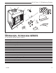
SR/SC Series "A" Woodburning Fireplace
7412948
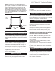
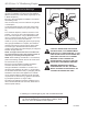
Hearth Installation
A hearth extension is required to protect a combustible
floor in front of the fireplace. Refer to Figure 23 for mini-
mum dimensions and mounting detail.
NOTE: Hearth Extension must not cover the air
inlet opening of a fireplace.
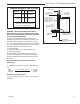
The hearth extension described in Figure 23 must be a
durable noncombustible material with a minimum (total)
Rt value of 1.09; refer to Figure 24 for examples. The
overall height (above a combustible floor), depth and
width must be as indicated, with the extension centered
to the fireplace opening.
The top of insulation must be covered with a noncom-
bustible decorative covering or a piece of .018” mini-
mum sheet metal, to protect hearth extension material.
(Fig. 23)
Secure the hearth extension to the floor to prevent
shifting, using trim molding or other similar means at
three (3) outer edges. Seal crack between the fireplace
hearth and hearth extension with a noncombustible
material. (Figs. 23 and 25)
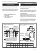
Minimum Wall Clearances
WITH
Noncombustible
Surround Facing
WITHOUT
Noncombustible
Surround Facing
Minimum Hearth Extension Dimensions
(for On-Site Construction)
G
H
G
J
Seal cracks
between the
fireplace
and hearth
extension with
noncombustible
material
Safety strips
must overlap
1/2" minimum
May install
noncombustible
decorative
covering
OR .018" min.
sheet metal
FIREPLACE
HEARTH
COMBUSTIBLE
FLOOR
MINIMUM
INSULATION
VALUE "R"
4" MIN.
FP594
SR/SC
11/20/97
FIREBOX
OPENING
A - Min. clearance
to combustible
perpendicular wall
B - Min. clearance
to combustible
perpendicular wall when
using noncombustible wall shield*
SIDE
WALL
SIDE
WALL
F**
C**
E
E
D
4" BRICK
(Example material)
Combustible material permitted within shaded area.
*
Noncombustible wall shield requires 1" MHSC EH2416
insulation (minimum R Value = 1.85) between decorative
noncombustible rigid covering and combustible wall.
Minimum height and width is 40" x 40".
**
Dimension/degree of angle will vary depending on thickness
of noncombustible surround facing.
4"
Shaded area starts
1/2" away from
edge of unit.
FP594
Fig. 23 Combustible side wall protection and hearth extension dimensions.
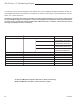
A B C D E F G H J
SR/SC36A 16" 12" 48° 41° 18" 14" 7³⁄₄" 16" 48"
406 mm 305 mm 457 mm 356 mm 197 mm 406 mm 1219 mm
SR/SC42A 20" 12" 42° 35° 18" 14" 11¹⁄₂" 20" 61¹⁄₂"
508 mm 305 mm 457 mm 356 mm 292 mm 508 mm 1562 mm
Side Wall Protection
Adjacent combustible side walls that are within the mini-
mum dimensions shown in Figure 23 of fireplace open-
ing must be protected with MHSC Wall Shield Model
SP40 or a specifically built wall shield described below.
The special wall shield design described in Figure 20 is
an alternate method of adding protection to side walls
and can be used in place of the SP40 with the same
wall clearances specified for the SP40. Rt must =1.85
minimum.
Examples of wall shield insulation:
1. Manville - CERAFORM 126, K=.27,
1/2 inches thick
2. MHSC - EH2416, K = .458,
1 inch thick required.