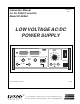
012-06263A Instruction Manual for the PASCO scientific Model SF-9584A 10/96 LOW VOLTAGE AC/DC POWER SUPPLY LOW VOLTAGE AC/DC POWER SUPPLY ¨ V A 10 VOLTAGE ADJUST DC + – 0 – 24 V 12 14 8 16 18 6 20 CURRENT ADJUST MAX DC CURRRENT 10 A 4 6A 12 V 24 V OFF AC SF-9584A 2 24 ON 22 RESET 2-24 V 6 A MAX © 1996 PASCO scientific $5.00 ̈ better 10101 Foothills Blvd. • P.O. Box 619011 • Roseville, CA 95678-9011 USA Phone (916) 786-3800 • FAX (916) 786-8905 • email: techsupp@PASCO.
CAUTION RISK OF ELECTRIC SHOCK DO NOT OPEN CAUTION TO PREVENT THE RISK OF ELECTRIC SHOCK, DO NOT REMOVE COVER ON UNIT. NO USER SERVICEABLE PARTS INSIDE. REFER SERVICING TO QUALIFIED SERVICE PERSONNEL. The lightning flash with arrowhead, within an equilateral triangle, is intended to alert the user of the presence of uninsulated “dangerous voltage” within the product’s enclosure that may be of sufficient magnitude to constitute a risk of electric shock to persons.
012-06263A Low Voltage AC/DC Power Supply Table of Contents Section Page Copyright, Warranty, and Equipment Return ...................................................... ii Introduction ....................................................................................................... 1 Operation ....................................................................................................... 1 - 2 Equipment Specifications .......................................................................
Low Voltage AC/DC Power Supply 012-06263A Copyright, Warranty and Equipment Return Please—Feel free to duplicate this manual subject to the copyright restrictions below. Copyright Notice Equipment Return The PASCO scientific 012-06263A manual is copyrighted and all rights reserved.
012-06263A Low Voltage AC/DC Power Supply Introduction The Low Voltage AC/DC Power Supply is intended for supervised classroom use. The PASCO scientific Model SF-9584A Low Voltage AC/DC Power Supply provides two outputs: a regulated DC output and an unregulated AC output. The DC output can be delivered in two modes: constant voltage mode and constant current mode. Operation DC Output, Limitations DC Output Operation: ➀ Flip the power ON/OFF switch to OFF.
Low Voltage AC/DC Power Supply 012-06263A AC Output Operation: AC Output Limitations ➀ Flip the power ON/OFF switch to OFF. The AC output is unregulated and is adjustable in 2-V increments from 2 to 24 V AC, with a maximum output current of 6 amperes. This output is protected by a 6-amp circuit breaker. If the maximum current output is exceeded, the circuit breaker button below the power switch will pop out. (See Figure 2.
012-06263A Low Voltage AC/DC Power Supply Equipment Specifications Specifications: Outputs: Ripple and Noise: Less than 25 mV pp on DC output. DC: regulated for both constant–voltage and constant–current operation. Both current and voltage continuously variable over the range 0–24 V DC and 0–10 amperes maximum. Independent floating ground reference. Metering: DC voltage and DC current Accuracy is +1% ± 2 L.S.D.
Low Voltage AC/DC Power Supply 012-06263A Notes: 4
012-06263A Low Voltage AC/DC Power Supply Schematics and Parts Lists ä Caution: If repairs are needed, they should be performed only by experienced personnel. Figure 2.
Low Voltage AC/DC Power Supply 012-06263A Figure 3.
012-06263A Low Voltage AC/DC Power Supply Parts List – Main Board Item 1 2 3 4 5 6 7 8 9 10 11 12 13 14 15 16 17 18 19 20 21 22 23 24 25 26 27 28 29 30 31 32 33 34 35 36 37 38 39 40 41 42 43 44 45 46 Reference R201 R204R206 R220-221 R205 R216 R219 R211 R214 R217 R227 R228 R218 R223 R226 R207 R230 R212 R213 R229 R222 R202-203 R208 R224 R210 R215 TR201-202 TR203-205 C229-234 C243-244 C213 C215 C235 C237-238 C240-241 C224-227 C214 C216-223 C228 C239 C211-212 C207-210 C236 C201-205 C206 D203 D205-209 D201-20
Low Voltage AC/DC Power Supply 012-06263A Figure 4.
012-06263A Low Voltage AC/DC Power Supply Parts List – Display Unit Item Reference 1 2 3 4 5 6 7 8 9 10 11 12 13 14 15 16 17 18 19 20 21 30 R101 R111 R107-108 R117-118 R120 R103 R113 R104 R114 R100 R102 R105-106 R110 R112 R115-116 P1-2 C103 C123 C112 C132 C109-110 C129-130 C102 C104 C106-10 C111 C122 C124 C126-128 C131 C105 C125 C101 C121 D101-102 DS101-108 D103-104 D105-106 U102 U104 U101 U103 SW101 J102-103 J101 U101 U103 Part Name Value Qty Stock No. RESISTOR RESISTOR 330R 1K0 250V 250V 0.
Low Voltage AC/DC Power Supply 012-06263A Figure 5.
012-06263A Low Voltage AC/DC Power Supply Parts List – Switch-Mode Regulator Item Reference Part Name 1 2 3 4 5 6 7 8 9 10 11 12 13 14 15 16 17 18 19 20 21 22 23 24 25 26 27 28 RESISTOR RESISTOR RESISTOR RESISTOR RESISTOR RESISTOR RESISTOR RESISTOR RESISTOR RESISTOR RESISTOR CERAMIC CAP CERAMIC CAP CERAMIC CAP STACK FOIL CAP STACK FOIL CAP ELECTROLYT CAP ELECTROLYT CAP ELECTROLYT DIODE ULTRA FAST DIODE DIODE DIODE BRIDGE ZENER-DIODE ZENER-DIODE NPN TRANSISTOR Pch MOSFET IC R3 Rl-2 R14 R10 R12 R9 R8 R5
Low Voltage AC/DC Power Supply 012-06263A Figure 6. Filter Board Parts List – Filter Board Item Reference Part Name 1 2 STACK FOIL CAP H1-4 C301-303 Value 100NF 12 Qty 400V 4 3 Stock No.
012-06263A Low Voltage AC/DC Power Supply Technical Support Feedback Contacting Technical Support If you have any comments about the product or manual, please let us know. If you have any suggestions on alternate experiments or find a problem in the manual, please tell us. PASCO appreciates any customer feedback. Your input helps us evaluate and improve our product.
012-05783A 2/95 $1.00 Instruction Sheet for the PASCO Model CI-6552A POWER AMPLIFIER II CAUTION! CI-6552A PLIFIER II POWER AM T PU L OUT SIGNA CI-6552A II LIFIER R AMP ION! POWE CAUT ON 0 V 0 to ±1 AX 1AM IS ON ED. LIGHT RT WHEN IS DISTO DE! FORM WAVE AMPLITU EASE DECR Introduction Filter Select Switch The PASCO CI-6552A Power Amplifier II is an accessory to the PASCO Signal Interfaces, Series 6500 and Mac65.
Power Amplifier II 012-05783A Equipment must be properly packed to prevent damage and shipped postage or freight prepaid. (Damage caused by improper packing of the equipment for return shipment will not be covered by the warranty.) Shipping costs for returning the equipment, after repair, will be paid by PASCO scientific.
012-03175E 3/93 Instruction Manual and Experiment Guide for the PASCO scientific Model ES-9054B ELECTROMETER FUNCTION B1 B2 3 D C 10 V O L T S 30 100 Model ES-9054B ELECTROMETER ZERO POWER scientific OFF OUTPUT © 1987 PASCO scientific GND INPUT ADJUST PUSH TO ZERO ON ZERO LOCK $7.
012-03175E Electrometer Table of Contents Section Page Copyright and Warranty ..................................................................................ii Equipment Return ...........................................................................................ii Introduction ..................................................................................................... 1 Operation .........................................................................................................
Electrometer 012-03175E Copyright, Warranty, and Equipment Return Please—Feel free to duplicate this manual subject to the copyright restrictions below. Copyright Notice Equipment Return The PASCO scientific 012-0xxxy Model Name manual is copyrighted and all rights reserved. However, permission is granted to non-profit educational institutions for reproduction of any part of the manual providing the reproductions are used only for their laboratories and are not sold for profit.
012-03175E Introduction The Model ES-9054B Electrometer is an infinite impedance (1014 ý) voltmeter that can be used for direct measurements of voltage, and indirect measurements of current and charge. Because of its high impedance, it is especially suited for measuring charge in electrostatic experiments. It has a sensitivity nearly 1,000 times that of a standard, gold-leaf electroscope, it has a center-zero meter that directly indicates charge polarity, and it measures charges as low as 10-11 coulombs.
012-03175E Mechanical zero adjust screw (adjust with power off) FUNCTION B1 B2 3 D C 10 V O L T S 30 100 Select voltage range (3, 10, 30, or 100 volts full scale) or test batteries (B1 and B2) Model ES-9054B ELECTROMETER ZERO POWER scientific OFF OUTPUT GND INPUT ADJUST PUSH TO ZERO ON ZERO LOCK Zero meter (zero switch should be in ZERO LOCK position) Zero Switch: In PUSH TO ZERO setting, pushing knob will discharge the electrometer Connect test lead here Connect to earth ground 0-3.
012-03175E Measuring Charge by Induction Under most conditions, the best way to measure charge is by induction, using a proof plane and a Faraday ice pail such as those included with PASCO’s Demonstration Electrostatics System. The proof plane is simply a small conductive disk on an insulating handle. You can make your own ice pail by mounting a conductive cylinder on an insulating support, and placing a larger conductive cylinder around it as a shield.
012-03175E To measure the total capacitance: inside cylinder of the ice pail, the Electrometer reading will generally remain relatively unchanged. This is because the total capacitance is only negligibly affected by the proof plane. This may not always be the case, however. ① Turn on the Electrometer and zero the meter. Clip the test lead of the probe to the inside cylinder of your ice pail and the ground lead to the outside cylinder (see Figure 4).
012-03175E ② Turn the ZERO ADJUST knob until the meter on the Electrometer reads as close to full scale as possible (either postive or negative). ③ Adjust the CALIBRATE knob on the Projection Meter so that the Projection Meter reads the same as the Electrometer. ④ Turn the ZERO ADJUST knob until the Electrometer and the Projection Meter read zero. PASCO’s Model ES-9065 Projection Meter can be used with an overhead projector to display the Electrometer readings for the whole class.
012-03175E ④ The replacement MOS-FET will probably come in Calibration an anti-static bag or may be wrapped in aluminum foil. The leads will be protected by a thin ring or spring that is wound around the leads near where they protrude from the base of the transistor. Gently remove the MOS-FET from the bag or foil, but do not remove the thin wire ring that is around the leads. Leave this wire ring in place until after the MOS-FET is seated in the socket.
012-03175E SCHEMATIC Model ES-9054B Electrometer (Drawing #956-02859) 7
012-03175E Parts List Reference R1,2,5,13, 20,21 R3 R4 R6,24 R7 R8 R9 R10,11,19 R12 R14 R15 R16 R17 R18 R22 R23 C1,3 C2,5 C4 C6 C7 Q1 Q2 U1 U2 S1 S2 M1 Description PASCO Part # Resistor, 10 ký, 1/4 W, 5% 113-103 Resistor, 1 ký, 1/4 W, 5% Resistor, 13 ký, 1/4 W, 5%, C.C. Resistor, 470 ý, 1/4 W, 5% Potentiometer, 10 ký, 1/4 W, 30% Resistor, 330 ý, 1/4 W, 5% Trimpot, 500 ý Resistor, 3.
012-03175E Electrometer Technical Support Feedback Contacting Technical Support If you have any comments about the product or manual, please let us know. If you have any suggestions on alternate experiments or find a problem in the manual, please tell us. PASCO appreciates any customer feedback. Your input helps us evaluate and improve our product.
012-01568C 12/94 $1.00 Instruction Sheet for the PASCO Model ES-9049A POWER SUPPLY Introduction When using the 1000 VDC range use the black and green binding posts. When the green binding post is used there is a 100 MΩ resistor in series with the output. This eliminates the hazard of shock if the green terminal is accidentally touched.
Power Supply 012-01568C Troubleshooting Tips ➀ No output on any range: CAUTION RISK OF ELECTRIC SHOCK DO NOT OPEN Fuse blown ➁ Low output on 1000 VDC range: CAUTION: TO PREVENT THE RISK OF ELECTRIC SHOCK, DO NOT REMOVE COVER ON UNIT. NO USER SERVICEABLE PARTS INSIDE. REFER SERVICING TO QUALIFIED SERVICE PERSONNEL. Defective capacitor C2, C3, C4, or C5. ➂ No output on 30 VDC range but other range is all right: Defective zener diode CR5 or power transistor Q1.
Power Supply 012-01568C PARTS LIST Specification Resistors: 22K, 1/4W, 5% 18K, 2W, 5% 1K, 2W, 5% 4.7M, 1/4W, 5% 150K, 1/2W, 1% 100M, 1/2W, 5% 4.99M, 1/2W, 1% POT, Two Section Capacitors: 10mF, 450V, Electrolytic .47mF, 400V, Mylar Transformer: Power, 115/230-2X115V Diodes/Semiconductors: 1N4007, 1000PIV, 1A Silicon Rect 1N4753A, 36V, 1W, 5% Zener LED Red Power Transistor RCA40412 NPN Switch: Slide, 4Pole, 3Position Fuse/Meter: .2A SLO-BLO (110-130VDC) .
Power Supply 012-01568C SCHEMATIC 4
Includes Teacher's Notes and Typical Experiment Results Instruction Manual and Experiment Guide for the PASCO scientific Model EM-8622 012-04367E 4/94 BASIC ELECTRICITY L DE MO -8622 EM C B CW A D E - + + C © 1990 PASCO scientific $10.00 better 10101 Foothills Blvd. • P.O.
012-04367E Basic Electricity Table of Contents Section ...........................................................................................................Page Copyright, Warranty, and Equipment Return ................................................. ii Introduction ..................................................................................................... 1 Equipment ........................................................................................................
Basic Electricity 012-04367E Copyright, Warranty and Equipment Return Please—Feel free to duplicate this manual subject to the copyright restrictions below. Copyright Notice Equipment Return The PASCO scientific Model EM-8622 Basic Electricity manual is copyrighted and all rights reserved. However, permission is granted to non-profit educational institutions for reproduction of any part of this manual providing the reproductions are used only for their laboratories and are not sold for profit.
012-04367E Basic Electricity Introduction The PASCO Circuits Experiment Board is designed to implement a large variety of basic electrical circuits for experimentation. The Circuits Experiment Board can be used for experiments beginning with a simple complete circuit and continuing on to a study of Kirchhoff’s Laws and characteristics of diodes and transistors. A labeled pictorial diagram of the Experiment Board appears in Figure 1.2 of Experiment 1.
Basic Electricity 012-04367E Getting Started ➀ Open the zip-lock bag containing the resistors and Store the remainder of the components in the ziplock bag until needed in future experiments. other components. Distribute the following resistors and wires to each of the boards, storing them in the plastic holder at the top of the board: ➁ Students will need to use the same resistors, same batteries, etc. from one experiment to another, particularly during experiments 4 to 6.
012-04367E Basic Electricity Comments on Meters VOM: VTVM: The Volt-Ohm-Meter or VOM is a multiple scale, multiple function meter (such as the PASCO SB-9623 Analog Multimeter), typically measuring voltage and resistance, and often current, too. These usually have a meter movement, and may select different functions and scales by means of a rotating switch on the front of the unit. The Vacuum Tube Voltmeter or VTVM is a multiple scale, multiple function meter, typically measuring voltage and resistance.
Basic Electricity 012-04367E Notes on the Circuits Experiment Board The springs are securely soldered to the board and serve as a convenient method for connecting wires, resistors and other components. Some of the springs are connected electrically to devices like the potentiometer and the D-cells. In the large Experimental Area, the springs are connected in pairs, oriented perpendicular to each other. This facilitates the connection of various types of circuits.
012-04367E Basic Electricity Experiment 1: Circuits Experiment Board EQUIPMENT NEEDED: -Circuits Experiment -D-cell Battery -Graph -Board -Wire Leads -Paper Purpose The purpose of this lab is to become familiar with the Circuits Experiment Board, to learn how to construct a complete electrical circuit, and to learn how to represent electrical circuits with circuit diagrams. Background ➀ Many of the key elements of electrical circuits have been reduced to symbol form.
Basic Electricity 012-04367E Procedure ➀ Use two pieces of wire to make connections between the springs on one of the light bulbs to the springs on the D-cell in such a way that the light will glow. Discuss with your lab partner before you begin actually wiring your circuit which connections you intend to make, and why you think you will be successful in activating the light.
012-04367E Basic Electricity Experiment 2: Lights in Circuits EQUIPMENT NEEDED: -Circuits Experiment Board -Wire Leads -Two D-cell Batteries -Graph Paper. Purpose The purpose of this lab is to determine how light bulbs behave in different circuit arrangements. Different ways of connecting two batteries will also be investigated.
Basic Electricity 012-04367E PART B ➆ Connect a single D-cell to a single light as in step 1, using a spring clip “switch” to allow you to easily turn the current on and off. Note the brightness of the light. ⑧ Now connect the second D-cell into the circuit as shown in Figure 2.1a. What is the effect on the brightness of the light? ➤ ➤ ➤ ➤ ➤ ➤ Figure 2.1a Figure 2.1b Figure 2.1c ⑨ Connect the second D-cell as in Figure 2.1b.
012-04367E Basic Electricity Experiment 3: Ohm’s Law EQUIPMENT NEEDED: -Circuits Experiment Board -Multimeter -Graph Paper. -D-cell Battery -Wire Leads Purpose The purpose of this lab will be to investigate the three variables involved in a mathematical relationship known as Ohm’s Law. Procedure ➀ Choose one of the resistors that you have been given. Using the chart on the back, decode the resistance value and record that value in the first column of Table 3.1.
Basic Electricity 012-04367E Data Processing ➀ Construct a graph of Current (vertical axis) vs Resistance. ➁ For each of your sets of data, calculate the ratio of Voltage/Resistance. Compare the values you calculate with the measured values of the current. Resistance, Ω Current, amp Voltage, volt Voltage/Resistance Table 3.1 Discussion ➀ From your graph, what is the mathematical relationship between Current and Resistance? ➁ Ohm’s Law states that current is given by the ratio of voltage/resistance.
012-04367E Basic Electricity Experiment 4: Resistances in Circuits EQUIPMENT NEEDED: -Circuits Experiment Boar - Multimeter -Resistors. Purpose The purpose of this lab is to begin experimenting with the variables that contribute to the operation of an electrical circuit. This is the first of a three connected labs. Procedure ➀ Choose the three resistors having the same value. Enter those sets of colors in Table 4.1 below. We will refer to one as #1, another as #2 and the third as #3.
Basic Electricity 012-04367E Series R1 R2 R3 R12= R23= ➤ R12 ➤ ➤ ➤ R23 R123= ➤ ➤ R123 Figure 4.1 ➅ Construct a PARALLEL CIRCUIT, first using combinations of two of the resistors, and then using all three. Measure and record your values for these circuits. Parallel R1 ➤ NOTE: Include also R13 ➆ Connect the COMBINATION ➤ CIRCUIT below and measure the various combinations of resistance.
012-04367E Basic Electricity 1st Colors 2nd 3rd Coded Measured 4th Resistance Resistance % Error A B C Table 4.2 Series RA RB RC RAB = RAB RBC = ➤ RBC ➤ ➤ RABC ➤ ➤ ➤ Figure 4.4 Parallel RA RAB RAB = ➤ ➤ RBC = RB RABC= RC Figure 4.
Basic Electricity 012-04367E Combination RB RA RA = RC RBC = ➤ ➤ RA ➤ ➤ RBC RABC RABC= ➤ Figure 4.6 Discussion ➀ How does the % error compare to the coded tolerance for your resistors? ➁ What is the apparent rule for combining equal resistances in series circuits? In parallel circuits? Cite evidence from your data to support your conclusions.
012-04367E Basic Electricity Experiment 5: Voltages in Circuits EQUIPMENT NEEDED: -Circuits Experiment Board -D-cell Battery -Wire Leads -Multimeter -Resistors Purpose The purpose of this lab will be to continue experimenting with the variables that contribute to the operation of an electrical circuit. You should have completed Experiment 4 before working on this lab.
Basic Electricity 012-04367E ➂ Now connect the parallel circuit below, using all three resistors. Measure the voltage across each of the resistors and the combination, taking care with the polarity as before. ➤NOTE: Keep all three resistors connected throughout the time you are making your measurements. Write down your values as indicated below. Parallel + - ➤ ➤ R1 R1 = V1 = R2 = V2 = R3 = V3 = R123 = V123 = V1 R2 R3 Figure 5.2 ➃ Now connect the circuit below and measure the voltages.
012-04367E Basic Electricity Series + - VA + RA RC RB - + - + - + ➤ ➤ VAB ➤ VBC VABC ➤ ➤ ➤ Figure 5.4 RA = VA = RB = VB = RC = VC = RAB = VAB = RBC = VBC = RABC= VABC= Parallel + - ➤ ➤ RA VA RB RA = VA = RB = VB = RC = VC = RABC= VABC= RC Figure 5.
Basic Electricity 012-04367E Combination + - RA = VA = RBC = VBC = RABC= VABC = RB RA RC ➤ VA ➤ VABC VBC ➤ ➤ ➤ ➤ Figure 5.6 Discussion On the basis of the data you recorded on the table with Figure 5.1, what is the pattern for how voltage gets distributed in a series circuit with equal resistances? According to the data you recorded with Figure 5.
012-04367E Basic Electricity Experiment 6: Currents in Circuits EQUIPMENT NEEDED: -Circuits Experiment Board -Resistors -Wire Leads. -Digital Multimeter -D-cell Battery Purpose The purpose of this lab will be to continue experimenting with the variables that contribute to the operation of electrical circuits.
Basic Electricity 012-04367E - I0 + + R1 - + - I 2 R3 R2 + I1 + - I3 - Figure 6.3 R1 = I0 = V1 = R2 = I1 = V2 = R3 = I2 = V3 = R12 = I3 = V12 = R23 = V23 = R123= V123= ➃ Connect the parallel circuit below, using all three resistors. Review the instructions for connecting the DMM as an ammeter in step 2. Connect it first between the positive terminal of the battery and the parallel circuit junction to measure I0.
012-04367E Basic Electricity Experiment 7: Kirchhoff’s Rules EQUIPMENT NEEDED: -Circuits Experiment Board -Wire Leads -Resistors. -Two D-cell Batteries -Digital Multimeter (DMM) Purpose The purpose of this lab will be to experimentally demonstrate Kirchhoff’s Rules for electrical circuits. Procedure ➀ Connect the circuit shown in Figure 7.1a using any of the resistors you have except the 10 Ω one. Use Figure 7.1b as a reference along with 7.1a as you record your data.
Basic Electricity 012-04367E Resistance, Ω Voltage, volts Current, mA R1 V1 I1 R2 V2 I2 R3 V3 I3 R4 V4 I4 R5 V5 I5 RT VT IT Table 7.1 Analysis ➀ Determine the net current flow into or out of each of the four “nodes” in the circuit. ➁ Determine the net voltage drop around at least three (3) of the six or so closed loops. Remember, if the potential goes up, treat the voltage drop as positive (+), while if the potential goes down, treat it as negative (-).
012-04367E Basic Electricity Experiment 8: Capacitors in Circuits EQUIPMENT NEEDED: – Vacuum Tube Voltmeter (VTVM) or Electrometer (ES-9054B) or Digital Multimeter (DMM) that has an input impedance of 10 MΩ or greater. – Circuits Experiment Board – Capacitors, Resistors – Wire Leads – D-cell Battery – Stopwatch or timer with 0.1 sec resolution. Purpose The purpose of this lab will be to determine how capacitors behave in R-C circuits. The manner in which capacitors combine will also be studied.
Basic Electricity 012-04367E Trial Resistance Capacitance tC tD 1 2 3 4 5 6 7 8 Table 8.1 ⑧ Replace the 100-µF capacitor with a 330-µF capacitor. Repeat step 7, recording the charging and discharging times in Table 8.1. If a third value is available, include it in the data table, too. ⑨ Return to the original 100-µF capacitor, but put a 220-K Ω resistor in the circuit. Repeat step 7, recording your data in Table 8.1. If a third resistor is provided, use it in the circuit, recording the data.
012-04367E Basic Electricity Experiment 9: Diodes EQUIPMENT NEEDED: -Circuits Experiment Board -Wire Leads -1000-Ω Resistor -330-Ω Resistor. -Digital Multimeter (DMM) -Two D-cell Batteries -1N4007 Diode Purpose The purpose of this lab will be to experimentally determine some of the operating characteristics of semiconductor diodes. Procedure ➀ Connect the circuit shown in Figure 9.1a using the 1N4007 diode you’ve been supplied and the 1000-Ω resistor. Use Figure 9.
Basic Electricity 012-04367E Discussion Discuss the shape of your graph and what it means for the operation of a semiconductor diode. Did the diode operate the same in steps 3 and 4 as it did in step 5? In steps 3 and 4 the diode was “Forward Biased”, while it was “Reverse Biased” in step 5.
012-04367E Basic Electricity Experiment 10: Transistors EQUIPMENT NEEDED: -Circuits Experiment Board -Wire Leads -1000-Ω Resistor -100-Ω Resistor. -Two D-cell Batteries -Digital Multimeter (DMM) -2N3904 Transistor (NPN) Purpose The purpose of this lab will be to experimentally determine some of the operating characteristics of a transistor. Procedure ➀ Connect the circuit shown in Figure 10.1a using the 2N3904 Transistor you’ve been supplied. Resistor R1 = 1000 Ω and resistor R2 = 100 Ω.
Basic Electricity 012-04367E Analysis ➀ For each of your sets of readings, calculate: IB = VAB / R1 and IC = VCD / R2 Record all of your current readings in mA. ➁ Plot a graph of IC (vertical axis) vs IB. If you find an area or areas where you need more points to fill out any curves or sudden changes, simply return to step 2 and make the appropriate measurements.
012-04367E Basic Electricity Appendix: Tips and Troubleshooting Correct Circuit, Doesn’t Work The labs asking for relative brightness ask students to judge relative brightness only, not an absolute brightness. This part of the experiment would be aided by having the room mostly darkened. Additional bulbs can be purchased from PASCO, at Radio Shack, an electronics store, at auto supplies stores, or possibly a local discount store.
Basic Electricity 012-04367E Wires Pulling the wire away from the stripper (Figure 3c) causes the cut end of the insulation to slip off of the wire, leaving 3/8" of exposed wire. The Circuits Experiment Board can be used with a large variety of wire types and sizes. We recommend 20 or 22 gauge solid wire with colorful insulation.
012-04367E Basic Electricity Replacement Parts List Item PASCO Part # P.C.B.
Basic Electricity 012-04367E Notes 32
012-04367E Basic Electricity Teacher's Guide Exp 1 - Circuits Experiment Board ➀ With this method, the lights will each be approximately the same brightness as in part 1. Serial: ➁ Reversing things at either end had no effect. ➃➄ There are two different ways of putting two lamps into the circuit: parallel and serial. Parallel: Using this circuit, the lights will be dimmer than in part 1. Exp 2 - Lights in Circuits ➃➄ ➤NOTE: It is best to do these experiments with both batteries, rather than just one.
Basic Electricity 012-04367E Exp 3- Ohm's Law Procedure 0.16 ➁-➅)Warn the students to be particularly careful when 0.14 setting up the multimeter to measure current. Attaching an ammeter the wrong way can damage the meter. Current 0.12 Data Processing Resistance 100 560 330 1000 10 Current 0.02 0.00 0.00 0.00 0.14 Voltage 1.579 1.582 1.582 1.583 1.549 J V/R % difference 0.02 -1.87% 0.00 -2.73% 0.00 -3.32% 0.00 -9.17% 0.15 -13.31% 0.1 0.08 0.06 0.04 0.
012-04367E Basic Electricity Colors A brown-black-brown-gold B orange-orange-brown-gold C green-blue-brown-gold coded 100 330 560 measured 98.9 330 561 % error -1.10% 0.00% 0.18% tolerance ±0.05% ±0.05% ±0.05% ➁-➃ In series, the resistances are added. R = R1 + R2 + R3 + ...In parallel, the reciprocals of the resistances are added. 1/R = 1/R1 + 1/R2 + 1/R3 +... This is evidenced in all the data sets above.
Basic Electricity 012-04367E Exp 6- Currents in Circuits ➤NOTE: R1 = R2 = R3 = The resistors used were: Discussion 100Ω 330Ω 560Ω In any resistance circuit—series, parallel, or both—the voltage, current, and resistance are related by Ohm’s Law: V = IR These are the same resistors as were used in the previous lab, and some of the data here originates in lab 5. This pattern, and conclusion, should be apparent in student data.
012-04367E Basic Electricity Analysis Second circuit: First circuit: ➀ node (2,3,4): ➀ node (1,3): -0.1 mA 0.1 mA node (b1,3,5): 0.1 mA node (1,2,5): 0.0 mA ➁ loop (b1,1,2,3) 0.001 V node (3,4,5): -0.1 mA loop (b2,5,3,4) 0.001 V node (2,4): 0.0 mA loop (b1,1,2,4,b2,5) 0.002 V ➁ loop (1,5,3): 0.001 V loop (1,2,4,3): 0.001 V loop (5,2,4): 0.000 V loop (batt,1,2): 0.001 V loop (batt,3,4): 0.000 V loop (batt,1,5,4): 0.001 V loop (batt,3,5,2): 0.
Basic Electricity 012-04367E Exp 9- Diodes Analysis The diode acts as a one-way valve for electricity. Current can flow in one direction, but not in the other. 0.007 Extensions 0.006 0.005 4007 J J LED J O ➀ A zener diode would be similar to the 4007, except that there would be a breakdown point on the reverse biasing, beyond which the current would flow. This makes them useful for power regulation. Current J O 0.004 J 0.003 0.002 0.
012-04367E Basic Electricity Technical Support Feed-Back Contacting Technical Support If you have any comments about this product or this manual please let us know. If you have any suggestions on alternate experiments or find a problem in the manual please tell us. PASCO appreciates any customer feedback. Your input helps us evaluate and improve our product.
012-04221C 11/94 $1.00 Instruction Sheet for the PASCO Model ES-9053A -6 .22 X 10 F 8 .50 X 10 Ω EXT INPUT 8 1.0 X 10 Ω 8 2.0 X 10 Ω RESISTOR -CAPACITOR NETWORK IN OPEN Two resistors and three capacitors are wired into a switching network, which allows selecting three resistance values (50 ΜΩ, 100 MΩ, and 200 MΩ) in series with two selectable capacitance values (0.47 µF and .94 µF). A third capacitor (0.22 µF) can be selected in series or parallel with the other two capacitances.
R-C Network 012-04221C Five binding posts allow a power supply, such as the PASCO Model ES-9049A Power Supply, and/or the electrometer to be connected at every possible component connection in the circuit. Plot time versus capacitor voltage for several values of R and C. What is the shape of the curve? Let us define T as the time required for the capacitor to charge from 10% to 90% of its final value. What is the relation between R,C, and T? (Hint: Convert R to ohms, C to farads, and T to seconds.
012-04221C R-C Network Specifications Equipment Return Resistance: Three selectable series values: 50 MΩ, 100 MΩ, and 200 MΩ; ±5% Tolerance Capacitance: Two selectable series values : 0.47 µF and .94 µF; One series/parallel value: 0.22 µF; ±5% Tolerance Should this product have to be returned to PASCO scientific, for whatever reason, notify PASCO scientific by letter or phone BEFORE returning the product. Upon notification, the return authorization and shipping instructions will be promptly issued.
R-C Network 012-04221C IN EXT INPUT EXT OPEN S3 C1 .22 µF ± 5% 100 V R1 100 MΩ GND S1 R2 100 MΩ 200M 100M 50M .22 µF OUT .94µF .47 µF GND C2 .47 µF, ± 5% 100 V GND ES-9053A SCHEMATIC 4 S2 C3 .
Instruction Manual and Experiment Guide for the PASCO scientific Model SF-8616 and 8617 012-03800A 11/89 COILS SET Copyright © November 1989 $15.
012-03800A How to Use This Manual The best way to learn to use the PASCO Basic Coils Set or the PASCO Complete Coils Set (referred to collectively as PASCO Coils Set) is to spend some time experimenting with it. We’ve organized this manual to get you started as quickly as possible. We strongly recommend that you read the Introduction and Experiments sections first. These are followed by 4 experiments for your students to get started on. The experiments are ready to send to the copy room.
012-03800A Equipment Supplied Your SF-8616 Basic Coils Set comes with the items shown in Figure 5a: a. (1) SF-8609 200-turn Coil b. (2) SF-8610 400-turn Coils c. (1) SF-8611 800-turn Coil d. (1) SF-8614 U-shaped Core e. (1) Manual Your SF-8617 Complete Coils Set comes with all of the items in the SF-8616 Basic Coils Set along with the following additional items, as shown in Figure 5b: f. (1) SF-8612 1600-turn Coil g. (1) SF-8613 3200-turn Coil h.
012-03800A Experiments Nature of Magnetic Field from an Electromagnet The coils from your PASCO Coils Set can be used in conjunction with a d.c. power supply or a battery to produce constant magnetic fields. Three possible experiments are shown below. • Figure 8b d.c. power ALTERNATIVE: Small magnetic compasses can be used to probe around the coil to show its magnetic field. compass amperes Figure 9 shows a current carrying coil with a magnetic field inside.
012-03800A Electromagnetic Induction showed a drop-off to an output voltage of less than 20% from the input voltage when the two 400-turn coils were used in this manner. Use a small, relatively strong bar magnet to demonstrate electromagnetic induction. It is only necessary to move the magnet up and down in the center of the coil. If the coil is attached to a galvanometer, the relative size of the induced current and the direction can be noted. See Figure 11.
012-03800A Experiment 1: Transformer Basics I Introduction When an alternating current passes through a coil of wire, it produces an alternating magnetic field. This is precisely the condition needed for the electromagnetic induction to take place in a second coil of wire. In this lab you will investigate several of the factors influencing the operation of a transformer. Equipment Needed - Supplied 1. 2. 3.
012-03800A Analysis 1. Which core configuration gives the maximum transfer of electromagnetic effect to the secondary coil? Develop a theory to explain the differences between configurations. 2. From your data in table 1.2, for a primary having a constant number of turns, graph the resulting output voltage versus the number of turns in the secondary. What type of mathematical relationship exists between numbers of turns of wire and the resulting output voltage? Is the data ideal? Why or why not? 3.
012-03800A Experiment 2: Transformer Basics II Introduction In this lab you will investigate several of the factors influencing the operation of a transformer. In Experiment 1, the output factor was voltage as measured when there was nothing connected to the secondary (infinite resistance). In this lab, you will investigate input and output currents, in addition to voltages, with normal sized resistances in the secondary circuit. Equipment Needed - Supplied 1. 2. 3.
012-03800A Note: Other configurations can be investigated once you have the E-shaped core. At your instructor’s direction, investigate other methods of arranging the primary and secondary coils. 8. If there are more than one PASCO Coils Sets in the laboratory, set up a series of transformers such as the one diagrammed below in Figure 4. Measure input and output voltages, input and output currents at various places in the chain.
012-03800A Data and Calculations Table 2.1 Number of Turns Trial # Primary Secondary Load R Input V Input I Output V Table 2.2 Trial # Input P Output P Voltage Gain Power Gain NOTE: It is recommended that the data collected above in Table 2.1 be gathered into a spread sheet program. Calculations of the input and output power, the voltage gain and power gain for Table 2.2 can quickly and easily be made using the spread sheet.
012-03800A Notes: 10 scientific
012-03800A Experiment 3: Springing into Electromagnetic Induction Introduction In this lab an interesting arrangement will allow you to investigate some of the subtelties of electromagnetic induction. The results will be qualitative, contrary to many of the labs you have done recently! Equipment Needed - Supplied 1. The PASCO Model SF-8616 Basic Coils Set Equipment Needed - Not Supplied 1. 2. 3. 4. 5.
012-03800A Analysis 1. Why did the magnets behave as they did? How does your observation relate to electromagnetic induction? 2. What was the effect of changing the polarity of the leads connecting the two coils? Why? 3. Why did the behavior change as a result of changing the mass of the magnet and/or the spring which was used? 4. Try to develop an explanation to cover the observations you made in steps 6-8.
012-03800A Experiment 4: Intermediate Transformers Introduction In this lab you will continue investigating transformers. You will investigate additional core configurations and work into d.c. power supplies, one of the key applications of transformer technology. Equipment Needed - Supplied 1. The PASCO SF-8617 Complete Coils Set Equipment Needed - Not Supplied 1. 2. 3. 4. 5. 6. 7. 8.
012-03800A Procedure B 7. Set up the 200-turn coil as primary, and the 800-turn coil as the secondary. Put a diode into the circuit as shown in Figure 4, and leave the 1000-Ω resistor in as a load. 8. In this step, set the triggering of your oscilloscope to “LINE”. This stabilizes the sweep so that it is sychronized with the a.c. line voltage. Now connect the ground lead (often a clip lead) from your oscilloscope to point A in Figure 3, and the probe to point B. Note the waveform.
012-03800A 15. The end result in step 14 is the production of a full-wave rectified signal, one which is directional in nature, although it varyies in amplitude over time. We will now add in a 470-µF capacitor as shown in Figure 7. Diode C • Load Resistor B • A Diode 16. What is the new waveform across the load resistor? Do you have d.c., yet? What is the d.c. voltage you’ve produced? Primary Figure 6 Diode 17. Now replace the 1000-Ω load resistance with a 10-Ω resistor.
012-03800A Appendix Technical Data PASCO Part No. SF-8609 SF-8610 SF-8611 SF-8612 SF-8613 Number of Turns in Coil Wire dia. mm 200 400 800 1600 3200 0.9 0.65 0.45 0.33 0.22 Maximum Current rms Amperes DC Resistance ohms 0.6 2.2 7.7 35.4 151 2A 1A 0.5 A 0.25 A 0.125 A 16 AC Impedance ohms 50 Hz 60Hz 0.64 2.4 8.7 39 164 0.65 2.5 9.1 40.5 170 Selfinductance mH 0.67 3.2 13.
012-04695D Thermal Radiation System Technical Support Feed-Back Contacting Technical Support If you have any comments about this product or this manual please let us know. If you have any suggestions on alternate experiments or find a problem in the manual please tell us. PASCO appreciates any customer feed-back. Your input helps us evaluate and improve our product.
012-04399C 3/95 $1.00 Instruction Sheet for the PASCO Model SF-8619 MAGNETIC DIP NEEDLE ➃ While in the horizontal position, rotate the entire appa- Introduction This compass needle is used to measure the dip angle of the Earth's magnetic field. However, it may also be used in its horizontal position as a conventional compass. ratus to align the compass needle with the axis of banana plug pivot.
Magnetic Dip Needle 012-04399C North Geographic Pole θ South Magnetic Pole Ι S N North Magnetic Pole θ = Angle read from Dip Needle I = Dip Angle = 90° - θ South Geographic Pole Dip Angle for Northern California Copyright Notice Limited Warranty The PASCO scientific Model SF-8619 Magnetic Dip Needle manual is copyrighted and all rights reserved.
012-04393B 11/95 $1.00 Instruction Sheet for the PASCO Model ES-9042A FARADAY ICE PAIL Introduction The Ice Pail designed by Faraday is an excellent product for sampling a charge distribution. It operates on the principle that a charge placed inside a conducting surface will induce an equal charge on the outside of that surface. For example, if a charged ball were hung inside a coffee can, the charge on the outside of the can would equal the charge of the ball.
Faraday Ice Pail 012-04393B ➁ Ground the ice pail (i.e., connect the inner pail to the ➤ NOTE: shield) by touching the inner pail and the outer shield at the same time with the finger of one hand. (See Figure 2) While conducting the experiment it may be convenient to continually rest one hand on the upper edge of the shield. This also grounds the experimenter, providing the electrometer is connected to both ground and shield and it allows the ice pail to be easily grounded whenever necessary.
012-05258B 10/94 $1.00 Instruction Sheet for the PASCO Model ES-9057A Charge Producers and Proof Planes Introduction The ES-9057A Charge Producers and Proof Planes are electrostatic components for use with additional equipment from the PASCO Electrostatics System ES-9062A. The two charge producers are used to generate equal positive and negative charges by contact. The two proof planes can be used to measure charge density on a charged object.
012-05258B Surface of the proof plane disk IS NOT tangent to the surface of the conductor. ➤ NOTE: You can then use an electrometer and a Faraday ice pail (ES-9042A) to measure the charge density on the proof plane, as shown in the following illustration. + Insert charged proof plane into Faraday ice pail Surface of the proof plane disk IS tangent to the surface of the conductor.
012-04929A 5/92 Instruction Sheet for the PASCO Model TD-8550A THERMOELECTRIC CONVERTER Introduction The PASCO scientific Thermoelectric Converter consists of a thermoelectric heat pump sandwiched between two aluminum metal legs. Electric current from the thermoelectric heat pump can drive a small motor that has a fan attached to its shaft. The Converter can demonstrate the Seebeck effect (discovered in 1821).
012-04929A This was Kelvin’s statement of the Second Law of Thermodynamics. The second law has been stated in many, seemingly unrelated ways; but in the end, all have been shown to be different ways of expressing the same basic principle. In its most general form, the Second Law tells us that no physical process will occur if it decreases the disorder—or entropy—of the universe. Conservation of energy, as expressed in the First Law of Thermodynamics, holds for every physical process.
012-04929A Peltier Effect: During the Peltier effect, a current through the thermoelectric heat pump of the Converter causes a temperature difference. Connect a DC power supply capable of 5 Volts and 3 Amps to the red and black terminals on the Converter. Put the switch on the Converter to the E → ∆T (down) position . (For this demonstration, you do not need to immerse the legs of the Converter in water.) Turn on the power supply.
012-04929A The electrons migrate, as shown, through the N-type semiconductor material and the holes migrate through the P-type material. (N and P type materials are merely silicon that is “doped” with special impurities that enhance electron and hole migration.) The electrons flow through the external circuit and drive the fan motor. At the other end of the circuit they reenter the cell and encounter the holes of the P-type semiconductor. This occurs near the cold end of the cell.