
Instruction manual


012-06263A Low Voltage AC/DC Power Supply
1
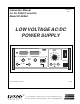
The PASCO scientific Model SF-9584A Low Voltage
AC/DC Power Supply provides two outputs: a regulated
DC output and an unregulated AC output. The DC out-
put can be delivered in two modes: constant voltage
mode and constant current mode.
Introduction
Operation
DC Output Operation:
➀ Flip the power ON/OFF switch to OFF.
➁ Plug the power cord into a grounded outlet of the ap-
propriate voltage :
Model SF-9584A, 115 V AC (78–130 V AC), 60 Hz
or
Model SF-9584A-230, 230 V AC (200 –242 V AC),
50 Hz.
➂ Connect the 0–24 V DC OUTPUT terminals of the
power supply to the circuit. (Connecting wires are not
provided with the power supply.)
➃ Rotate the DC VOLTAGE ADJUST knob and the DC
CURRENT ADJUST knob fully counterclockwise.
➄ Flip the power ON/OFF switch to ON. The switch
will light to show that the power supply is on.
➅ Constant Voltage Mode: Turn the DC CURRENT
ADJUST knob fully clockwise. Then adjust the DC
VOLTAGE ADJUST knob to obtain the desired out-
put voltage, as indicated on the meter. The output cur-
rent is displayed on the current meter.
➆ Constant Current Mode: Turn the DC VOLTAGE
ADJUST knob fully clockwise. Adjust the DC CUR-
RENT ADJUST knob to obtain the desired output
current, as indicated on the meter. The output voltage
is displayed on the voltage meter.
Figure 1. Maximum DC Current
6 A
10 A
12 V
24 V
MAX DC CURRRENT
The Low Voltage AC/DC Power Supply is intended for
supervised classroom use.
DC Output, Limitations
The DC output is regulated for both constant-voltage and
constant–current operation.
Constant Voltage mode:
The voltage is continuously variable from 0 –24 V DC.
The maximum load drawn in the range from 0–12 V DC
is 10 A. In the 12 - 24 V range, a load of 10–6 A may be
drawn as the maximum load. At 24 V, the maximum is 6
A. (See the illustration printed on the front panel, “Max.
DC Current,” or Figure 1.)
Constant Current mode:
The load may be varied from 1–10 A in the 1–12 V DC
range. At 12 V, the DC range is variable from 1–10 A.
At 24 V, the range decreases to 0–6 A. (See the illustra-
tion printed on the front panel, “Max. DC Current,” or
Figure 1.) A digital meter allows monitoring of both
voltage and current for the DC output.