Analog Memory 1
Limited WARRANTY: Make Noise warrants this product to be free of defects in materials or construction for a period of two years from the date of manufacture. Malfunction resulting from wrong power supply voltages, backwards power cable connection, abuse of the product or any other causes determined by Make Noise to be the fault of the user are not covered by this warranty, and normal service rates will apply.
Installation: The Make Noise Analog Memory is an electronic signal generator requiring 20mA of +12V regulated power and properly formatted distribution receptacle to operate. It is designed to be used within the euro format modular synthesizer system. Go to http://www.doepfer.de/a100_man/a100t_e.htm for the details of this format. To install, find 20HP of space in your euro-rack synthesizer system directly above or adjacent to the Pressure Points which will connect to the Analog Memory.
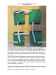
EXPAND Cable: The expand cable has four 10 x 2 female connector on a flat grey cable with one Red Stripe. One end of this cable is attached to the Pin Header on the back of the Analog Memory where it says “Connect to EXPAND.” Orient the Red Stripe Down for easy installation.
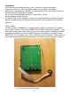
Connection to Single Pressure Points Connect one of the remaining 3 connectors to the 10 pin header on the Pressure Points that is marked “EXPND.” You will need to remove all 4 of the small black “jumpers” that are covering the pins of this header before you attach the EXPAND CABLE. NOTE: Power Cables removed in photo for clarity.
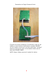
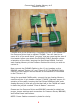
Connecting 2 Analog Memory to 2 Pressure Points Connect one of the remaining 3 connectors to the 10 pin header on the Pressure Points that is marked “EXPND.” You will need to remove all 4 of the small black “jumpers” that are covering the pins of this header before you attach the EXPAND CABLE. Maintain proper orientation of the cable, keeping the Red Stripe DOWN. Connect each Analog Memory to the Pressure Points with which you wish to control it.
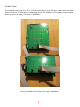
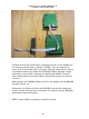
Connecting Analog Memory to Pressure Points/ BRAINS system Before connecting to the Pressure Points/ BRAINS system, you will need to remove the 4 jumpers along the bottom of the backside of the Analog Memory.
Connecting 1 Analog Memory to Pressure Points/ BRAINS Connect one of the remaining 3 connectors to the 10 pin header on the Pressure Points that is marked “EXPND.” You will need to remove all 4 of the small black “jumpers” that are covering the pins of this header before you attach the EXPAND CABLE. Maintain proper orientation of the cable, keeping the Red Stripe DOWN. Connect each Analog Memory to the Pressure Points with which you wish to control it.
Connecting 2 Analog Memory to 2 Pressure Points Connect one of the remaining 3 connectors to the 10 pin header on the Pressure Points that is marked “EXPND.” You will need to remove all 4 of the small black “jumpers” that are covering the pins of this header before you attach the EXPAND CABLE. Maintain proper orientation of the cable, keeping the Red Stripe DOWN. Connect each Analog Memory to the Pressure Points with which you wish to control it.
OVERVIEW The Analog Memory module uses an innovative new data storage technology called “Mechanically Orbited Carbon,” to store and recall control voltage values for use within the modular synthesizer system. The MOC RAM technology has the advantage of completely passive non-volatile storage! Power is only used in the generation of the recalled voltage values for use within the modular synthesizer system.
2 1 3 11
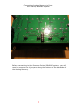
1. Potentiometers for progamming Voltage Values. 2. Voltage OUTPUTS. Topmost output 0V-8V all others 0V 5.5V These outputs are buffered so that they may drive multiple destinations with out loading affects (dropping). 3. Selected Column Indicators. 1 of these 4 LEDs will light to indicate active column. The Analog Memory must be used with Pressure Points or a Pressure Points/ BRAINS system. using the Analog Memory in a patch is simple.