
Owner manual
12
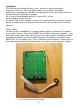
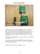
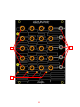
1. Potentiometers for progamming Voltage Values.
2. Voltage OUTPUTS. Topmost output 0V-8V all others 0V 5.5V These outputs are buff-
ered so that they may drive multiple destinations with out loading affects (dropping).
3. Selected Column Indicators. 1 of these 4 LEDs will light to indicate active column.
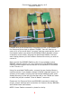
The Analog Memory must be used with Pressure Points or a Pressure Points/ BRAINS
system. using the Analog Memory in a patch is simple. Patch any of the Voltage OUT-
PUTS to just about any number of CV INPUTS in your system. Set the attenuator (if
any) associated with the CV input, to at least 10% so that you may add the voltage
from the Analog Memory to the other voltages being used to control the associated
parameter. Starting with column 1, program the desired voltage using the associated
potentiometer on the Analog Memory. Select the next column and do the same, until
all columns have been programmed.