DPO
Limited WARRANTY: Make Noise warrants this product to be free of defects in materials or construction for a period of one year from the date of purchase (proof of purchase/invoice required). Malfunction resulting from wrong power supply voltages, backwards power cable connection, abuse of the product or any other causes determined by Make Noise to be the fault of the user are not covered by this warranty, and normal service rates will apply.
Installation: The Make Noise DPO is an electronic signal generator requiring 70mA of +/-12V of regulated power and properly formatted distribution receptacle to operate. It is designed to be used within the euro format modular synthesizer system. Go to http://www.doepfer.de/a100_man/a100t_e.htm for the details of this format.
Overview: The DPO is a voltage controlled oscillator designed for generating complex waveforms and implementing FM synthesis within the analog domain. Expanding on the classic arrangement of Primary and Modulator Oscillators, the DPO has both of the VCOs operable as complex signal sources. It is in essence a Dual Primary Oscillator. The DPO is also designed for fast live sound creation.
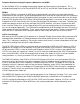
1A 2A 3A 1B 2B 3B 4A 4B 5A 5B 6A 6B 7A 7B 12A 8B 8A 12B 9A 10A 11A 9B 10B 11B VCO A 1A Triangle Waveform OUT: 10Vpp 2A Sawtooth Waveform OUT: 9Vpp 3A Sine Waveform OUT: 10Vpp 4A Coarse Tune panel control: 9.5 octave range 12hz-6khz 5A 1V/ Octave Scale Trimmer (see calibration procedure) 6A Fine Tune panel control: 1.
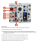
1 2 3 4 5 6 7 VCO Interaction 1. Beat Frequency LED: visual indication of Phase difference between VCOs A & B. 2. FOLLOW CV INput: unipolar control input. Range 0V to 5V. 3. FOLLOW Attenuator: determines how well VCO A will FOLLOW VCO B. With nothing patched to FOLLOW CV IN works as standard panel control. With Signal Patched to FOLLOW CV IN, works as an attenuator for that signal. 4. FM BUS INDEX: unipolar panel control that sets the index (depth) of the FM. 5.
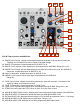
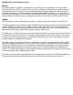
1A 2A 3A 1B 2B 3B 1C 2C 3C 4C 1D 2D 3D 4D 5D VCO B Timbre Controls and MOD Bus 1A. SHAPE Panel Control: unipolar control that determines the shape of the waveform feeding the FOLDing circuit. Morphs from Sine to Spike to Glitched Triangle. 2A. SHAPE CV Attenuator: unipolar attenuator for SHAPE CV IN. 3A. SHAPE CV IN: unipolar control signal input. Normalled into the MOD BUS. Range 0V to +5V. 1B. ANGLE Panel Control: tilts the added harmonics to either end of the wave-cycle. 2B.
Complex Waveforms through Frequency Modulation and SYNC: On the DPO both VCOs are capable of generating complex and harmonically rich waveforms. This is accomplished through the use of FM and HARD SYNC on VCO A, and FM and Timbre Shaping on VCO B.
VCO B core behavior There is one way to affect the behavior of the VCO B core. The eXternal LOCK input allows for an extremely weak, phase reversed synchronization of VCO B to an external VCO where as VCO B approaches an integer frequency of the applied external VCO, VCO B will reset to match the external VCO, and thus small tuning errors will be corrected.
MOD BUS and Timbre Shaping Sections: Mod Bus The internal Mod Bus SOURCE is hardwired for VCO A SINE wave, with the power to use any external source by patching to the EXT. SouRCe Input. The internal MOD bus system makes use of the Normalization Switch found on the mini-jacks, so with nothing patched to the Shape, Angle and Fold CV inputs the associated attenuator sets the final amount of modulation applied to the destination.
The phase reversal and Amplitude Modulation that occurs around the 50% range of the SHAPE parameter value is useful on it’s own (before FOLDing occurs) for subtle and pleasing modulations via LFO. The SHAPE circuit is slow and smooth with a unique response quite unlike the typical balanced modulator or VCA. When this element of the SHAPE circuit is utilized with FOLDing, the AM and Phase Reversal will act to drop and/ or reverse folds resulting in deeper animation of the Timbre.
The OTHER WAVEFORM OUTPUTS In addition to the FINAL out there are several wave shapes that are all tapped or derived from the oscillator cores. Except for the VCO A SAW and VCO B SQUARE, these signals are all around 10V peak to peak and centered around 0V (bi-polar). The SINE wave is derived from the TRIANGLE core of both oscillators and is provided as an output for both VCO A and B because it is great for blending with signals of greater harmonic content in order to strengthen the fundamental.
Patch Ideas: Animated Lead: Patch sequencer or keyboard CV to VCO B 1V/ Octave INput. Monitor VCO B FINAL OUT. Set SHAPE and ANGLE panel controls and CV Attenuators to NOON. Set FOLDS to 9 o' Clock and set FOLDS CV attenuator to NOON. Set Mod Bus panel control to NOON. Patch Gate from sequencer or CV KB to STRIKE INput of DPO. Push button to select LFO behavior at VCO A. Set VCO A FREQ. to around 9 o' Clock and set Follow p to full clockwise (100%).
1A 1B 2B 2A 3B 3A 4B 4A 5 6 Calibrating the DPO Requires small flat head screw driver or trimmer tool, tuned reference signal, oscilloscope. NOTE: if you plan to use the DPO with another VCO or Synth in your system (even another DPO), it is a good idea to use that VCO/ Synth for your reference signal, assuming it is calibrated to your satisfaction. The same is true of the quantizer or MIDI to CV interface. Use the unit within your system.
1A 1B 2B 2A 3B 3A 4B 4A 5 6 7. To calibrate VCO A 1V/ Octave Scale, use VCO B (that is now tuned) as reference. 8. Monitor VCO A and B SINEs. Patch or Midi to CV to VCO A 1V/ Octave INput (6), and FOLLOW (5) still at 0%. 9. Send note C6 to the DPO and adjust the VCO A FREQ (2A) and FINE TUNE (4A) Panel Controls so the DPO VCO A pitch matches that of the reference (DPO VCO B). 10.
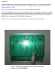
1A 2A 3A 1B 2B 3B 4A 6A 4B 6B VCO SINE Shape and Amplitude Trims for SINE shape (1A, 1B) and Amplitude (3A, 3B) are accessed through the top side of the module. Take care in lifting the top half of the module out of case for calibration. 1.Monitor the SINE (2A, 2B) from the VCO to be calibrated. If possible view the signal on an oscillo\ scope and/ or spectrum analyzer as well. 2. Set VCO to be calibrated near to frequency of C4. (4A, 4B) 3. Set oscilloscope for 2V/ div. by 2ms/ div.
1 2 3 4 5 Calibrating the VCO B FINAL OUT Trims for FINAL OUT are SHAPE Balance (3) which is accessed through the top side of the module and FOLD Gain (4) which is accessed through the right side of the module. Take care in lifting the module out of case for calibration. 1. Before this calibration may be performed, the SINE Shape and Amplitude calibration must be completed. 2. Monitor the VCO B FINAL OUT (2) and view the signal on an oscilloscope set for 2V/ div. by 2ms/ div. 3.