
User Manual


4B
6B
1A
4A
6A
2A
3A
1B
2B 3B
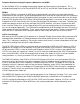
VCO SINE Shape and Amplitude
Trims for SINE shape (1A, 1B) and Amplitude (3A, 3B) are accessed through the top side of the module.
Take care in lifting the top half of the module out of case for calibration.
1.Monitor the SINE (2A, 2B) from the VCO to be calibrated. If possible view the signal on an oscillo\
scope and/ or spectrum analyzer as well.
2. Set VCO to be calibrated near to frequency of C4. (4A, 4B)
3. Set oscilloscope for 2V/ div. by 2ms/ div. (skip to step 4. if no oscilloscope will be used).
4. Trim SINE Shape (1A, 1B) for least amount of audible harmonics (skip to step 5 if using oscilloscope).
5. If using an oscilloscope or spectrum analyzer adjust so the SINE shape is pure as possible, meaning
both the top and bottom arches are smooth, rounded and glitch free, and harmonics are minimized.
6. Amplitude is adjusted by trim 3A, 3B. Amplitude should be set using oscilloscope for measurement, to
roughly 10.5V peak to peak for VCO A and roughly 10.2V peak to peak for VCO B. There is some
cases where amplitude of VCO B will need to be greater or less than the above specification in order
for the, FM Bus and Fold circuits to operate correctly. See the last step of the VCO B FINAL OUT
Calibration for more details.
NOTE: Amplitude should not require adjustment in most cases.
Expect some small amount of harmonics in the SINE shape. Trim to satisfaction and then go make noise!