
User Manual


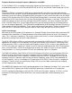


1
2
7
3
4
5
6
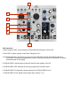
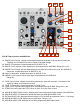
VCO Interaction
1. Beat Frequency LED: visual indication of Phase difference between VCOs A & B.
2. FOLLOW CV INput: unipolar control input. Range 0V to 5V.
3. FOLLOW Attenuator: determines how well VCO A will FOLLOW VCO B. With nothing patched to
FOLLOW CV IN works as standard panel control. With Signal Patched to FOLLOW CV IN, works
as an attenuator for that signal.
4. FM BUS INDEX: unipolar panel control that sets the index (depth) of the FM.
5. FM BUS INDEX LED: indicates the currently programmed FM Index Value.
6. FM BUS INDEX CV Attenuator: bipolar attenuator for FM BUS INDEX CV IN
7. FM BUS INDEX CV IN: bipolar control signal input. Range +/- 4V