
Instruction Manual


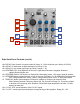


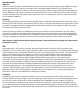

Erbe-Verb Panel Controls
1a. Signal IN: AC coupled, expects standard signal level of 10Vpp signal.
1b. Level Control for Signal IN: unity at 3 o' Clock
2a. MIX CV IN: unipolar control input. Range 0V to +5V.
2b. MIX Panel Control: blends between DRY (un-processed) signal & WET (processed) Signal. Operates as
Combo Knob, with nothing patched to MIX CV IN, works as standard panel control. With
Signal Patched to MIX CV IN, works as attenuator for that signal.
3a. Left (MONO) Output: 10Vpp (depending upon Level setting and source material), AC coupled. Left portion
of Stereo reverb image, also serves as MONO reverb image.
3b. Right Output: 10Vpp (depending upon Level setting and source material), AC coupled. Right portion of
Stereo reverb image.
4a. SIZE Panel Control: unipolar panel control that sets the Size of the space. Ranges from "coffin" to
"heavens." 35 cu. ft. - 9.3 million cu. ft.
4b. SIZE CV Attenuator: bi-polar attenuator for Size CV IN.
4c. SIZE CV IN: control signal input for Size. Range +/- 5V.
5a. SPEED Panel Control: uni-polar control for Speed of internal modulation.
Using internal clock: 1/2cps - 256 cps, using ext. clock 1/48cps - 9000 cps
5b. SPEED LED: visual indication of Internal Modulation rate.
5c. SPEED CV IN: control signal input for Speed. Range +/- 5V.
6a. DEPTH Panel Control: bi-polar control for Depth and Type of Internal Modulation. Minimum modulation at NOON. Cyclic modulation CCW from NOON. Ergodic modulation CW from NOON. Shimmer at Full CW.
6b. DEPTH CV Attenuator: bi-polar attenuator for Depth CV IN.
6c. DEPTH CV IN: control signal input for Depth. Range +/- 5V.
7a. PRE-DELAY Panel Control: control for amount of Pre-Delay. Using int. clock operates as uni-polar w/ range 7ms - 500ms. Using ext. clock operates as bi-polar w/ divisors & multipliers of 1/12, 1/8, 1/6, 1/4, 1/3, 1/2, 2/3, 1/1, 3/2, 2/1, 3/1, 4/1, 6/1, 8/1, 12/1 where 1/1 is at NOON.
7b. PRE-DELAY CV IN: control signal input for Pre-Delay. Range +/- 5V.
8a. TILT Panel Control: bi-polar control for Tilt. Low Gain +12 dB to -12 dB, High Gain -24dB to + 24dB, unity at NOON.
8b. TILT CV Attenuator: bi-polar attenuator for Tilt CV IN.
8c. TILT CV IN: control signal input for Tilt. Range +/- 5V.
9a. ABSORB Panel Control: uni-polar control for Absorption. Full CCW = 0 diffusion, 0 damping; 10 o'clock = full diffusion, 0 damping; Full CW = full diffusion, full damping.
9b. ABSORB CV IN: control signal input for Absorption. Range +/- 5V.
10a. DECAY Panel Control: uni-polar control for Decay. 0 - 120% reflection gain. Infinity at Full CW.
10b. DECAY CV Attenuator: bi-polar attenuator for Decay CV IN.
10c. DECAY CV IN: control signal input for Decay. Range +/- 5V.
11a. REVERSE LED: visual indication of Reverse. Lights when Reverse is engaged, flickers to indicate Reverse buffer rate.
11b. REVERSE Gate IN: will Reverse on Gate HIGH. Momentary action. 1.5V trigger signal to operate.
11c. REVERSE Button: toggles Reverse on/ off. In Reverse Pre-Delay (7a, 7b) determines Reverse buffer size. Using int. clock: 42ms - 500ms, using ext. clock: 0.1ms - 5.46s synchronized
12a. TEMPO IN: allows synchronization of Echoes to multiple or division of an external Clock. While following external Tempo the Speed (5a, 5b, 5c) and Pre-Delay (7a, 7b) will be multiple or division of the incoming clock. Requires Clock/ Gate signal amplitude of at least 1.5V and width of at least 6ms.
13a. CV OUT LED: visual indication of the CV OUT signal.
13b. CV OUT: control signal representing the average energy of the algorithm. Range 0V - 10V
1b
2a
1a
3a
3b
2b
4b
4c
5c
4a
5b
5a