
Owner manual


SUM and OR Bus (cont’d)
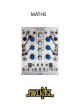
7. CH. 1 Variable OUT: The applied signal as processed by CH. 1 controls. Normalized to the SUM and OR
busses. Inserting a patch cable will remove the signal from the SUM and OR busses. Output Range +/-10V
8. CH. 2 Variable OUT: The applied signal as processed by CH. 2 controls. Normalized to the SUM and OR
busses. Inserting a patch cable will remove the signal from the SUM and OR busses. Output Range +/-10V
9. CH. 3 Variable OUT: The applied signal as processed by CH. 3 controls. Normalized to the SUM and OR
busses. Inserting a patch cable will remove the signal from the SUM and OR busses. Output Range +/-10V
10. CH. 4 Variable OUT: The applied signal as processed by CH. 4 controls. Normalized to the SUM and OR
busses. Inserting a patch cable will remove the signal from the SUM and OR busses. Output Range +/-10V
11. OR Bus OUT: Result of the
Analog Logic OR function with respect to the settings of the attenuvertor
controls for channels 1, 2, 3 and 4. Range 0V to 10V.
12. SUM Bus OUT: Sum of the applied voltages with respect to the settings of the attenuvertor controls for
channels 1, 2, 3 and 4. Range +/-10V
13. INVerted SUM OUT: signal from SUM OUT turned upside down. Range +/-10V
14. SUM Bus LEDs: indicate voltage activity in the SUM bus (and therefore the INVerted SUM as well). RED
LED indicates negative voltages. GREEN LED indicates positive voltages.
1
3
14
7
2
4
5
6
8
11
12
13
14
10
9