v2.
MATHS Limited Warranty ----------------------------------------------------3 Installation ----------------------------------------------------------4 Overview ---------------------------------------------------------5 Channel 1 Panel Controls -----------------------------------------6 Channel 4 Panel Controls --------------------------------------------8 SUM and OR Bus -----------------------------------------------------10 Getting Started -------------------------------------------------------12 Rise,
Limited WARRANTY: 3 Make Noise warrants this product to be free of defects in materials or construction for a period of one year from the date of purchase (proof of purchase/invoice required).
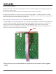
Electrocution hazard! Always turn the Eurorack case off and unplug the power cord before plugging or unplugging any Eurorack bus board connection cable. Do not touch any electrical terminals when attaching any Eurorack bus board cable. The Make Noise MATHS is an electronic music module requiring 60mA of +12VDC and 50 mA of -12VDC regulated voltages and a properly formatted distribution receptacle to operate. It must be properly installed into a Eurorack format modular synthesizer system case.
Overview: 5 MATHS is an analog computer designed for musical purposes. Amongst other things, it allows you to: 1. Generate a variety of linear, logarithmic, or exponential triggered or continuous functions 2. Integrate an incoming signal 3. Amplify, attenuate and Invert an incoming signal 4. Add, subtract and OR up to 4 signals 5. Generate analog signals from digital information (Gate/Clock) 6. Generate digital information (Gate/Clock) from analog signals 7.
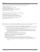
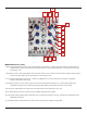
2 1 3 5 7 14 15 4 6 8 9 10 11 12 13 MATHS Channel 1 1. Signal Input: Direct Coupled input to circuit. Use for Lag, Portamento, ASR (Attack Sustain Release type envelopes). Also input to Sum/OR Bus. Range +/-10V 2. Trigger Input: Gate or Pulse applied to this input triggers the circuit regardless of activity at the Signal Input. The result being a 0V to 10V function, aka Envelope, whose characteristics are defined by the Rise, Fall, and Vari-Response parameters.
2 1 3 5 7 14 15 4 6 8 9 10 11 12 13 MATHS Channel 1 (Cont’d) 8. Both CV Input: Bi-Polar Exponential control signal input for entire function. Contrary to the Rise and Fall CV Inputs, BOTH has an Exponential response and Positive control signals decrease total time while Negative control signals increase total time. Range +/-8V 9. Fall CV Input: Linear control signal input for Fall parameter.
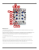
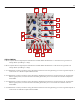
2 7 1 5 4 3 6 8 9 10 11 12 15 14 13 MATHS Channel 4 1. Signal Input: Direct Coupled input to circuit. Use for Lag, Portamento, ASR (Attack Sustain Release type envelopes). Also input to SUM/OR Bus. Range +/-10V 2. Trigger Input: Gate or Pulse applied to this input triggers the circuit regardless of activity at the Signal Input. The result being a 0V to 10V function, aka Envelope, whose characteristics are defined by the Rise, Fall, and Vari-Response parameters.
2 7 1 5 4 3 6 8 9 10 11 12 15 14 13 MATHS Channel 4 (cont’d) 8. Both CV Input: Bi-Polar Exponential control signal input for entire function. Contrary to the Rise and Fall CV Input, Both has an Exponential response and Positive control signals decrease total time while Negative control signals increase total time. Range +/-8V 9. Fall CV Input: Linear control signal input for Fall parameter.
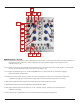
1 2 3 4 5 9 6 8 7 14 12 11 14 10 13 SUM and OR Bus 1. Direct Coupled Channel 2 Signal Input to Attenuverter and Sum/OR Bus. Normalized to a +10V reference for generation of voltage offsets. Input Range +/-10Vpp. 2. Direct Coupled Channel 3 Signal Input to Attenuverter and Sum/OR Bus. Normalized to a +5V reference for generation of voltage offsets. Input Range +/-10Vpp. 3. CH.
1 2 3 4 5 9 6 8 7 14 12 11 14 10 13 SUM and OR Bus (cont’d) 7. CH. 1 Variable Output: The applied signal as processed by CH. 1 controls. Normalized to the SUM and OR busses. Inserting a patch cable removes the signal from the SUM and OR busses. Output Range +/-10V 8. CH. 2 Variable Output: The applied signal as processed by CH. 2 controls. Normalized to the SUM and OR busses. Inserting a patch cable removes the signal from the SUM and OR busses. Output Range +/-10V 9. CH.
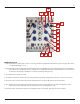
Getting Started 12 MATHS is laid out top to bottom, with symmetrical features between CH. 1 and 4. The signal inputs are at the top, followed by the panel controls and control signal inputs at the middle. The signal outputs are at the bottom of the module. LEDs are placed near the signal they are indicating. Channels 1 and 4 are able to scale, invert or integrate an incoming signal.
Rise/Fall/Vari-Response 13 These controls shape the signal that is output at the Unity Signal Output and Variable Outputs for CH. 1 and 4. The Rise and Fall controls determine how fast or slow the circuit responds to signals applied to the Signal Input and Trigger Input. The range of times is larger than the typical Envelope or LFO. MATHS creates functions as slow as 25 minutes (Rise and Fall full CW and external control signals added to go into "slow-ver-drive") and as fast as 1khz (audio rate).
Signal Outputs 14 There are many different signal outputs on the MATHS. All of them are situated at the bottom of the module. Many of them have LEDs situated nearby for visual indication of the signals. The Variable Outs These outputs are labeled 1, 2, 3 and 4 and are associated with the four Attenuverter controls in the center of the module. These outputs are all determined by the settings of their associated controls, esp. the CH. 1 through 4 Attenuverter controls.
Tips & Tricks 15 -Longer cycles are achieved with more Logarithmic response curves. The fastest, sharpest functions are achieved with extreme Exponential response curves. -Adjustment to the response curve affects Rise and Fall Times. -To achieve longer or shorter Rise and Fall Times than available from Panel Controls, apply a voltage offset to the Control Signal Inputs. Use CH. 2 or 3 for this offset voltage.
Patch Ideas: Analog Signal Processing, Voltage MATHS! Typical Voltage Controlled Triangle Function (Triangle LFO) Set CH. 1 (or 4) to Cycle. Set Rise and Fall Panel Control to 12:00, Vari-Respnose to Linear. Set CH. 2 Attenuverter to 12:00. Patch SUM Output to Both Control Input. Optionally, apply any desired frequency modulation to the CH. 3 Signal Input and slowly turn it’s attenuator clockwise. Increase the CH. 2 Attenuverter to change the Frequency.
Patch Ideas: Analog Signal Processing, Voltage MATHS! Voltage Controlled Sustained Function Generator (A/S/R EG) A gate applied to the Signal Input of CH. 1 or 4 starts the function which Rises from 0V to the level of the applied Gate, at a rate determined by the Rise parameter, Sustains at that level until the Gate signal ends, and then falls from that level to 0V at a rate determined by the Fall parameter.
Patch Ideas: Analog Signal Processing, Voltage MATHS! Half Wave Rectification Apply bi-polar signal to CH. 1, 2, 3, or 4 Inputs. Take output from OR Output. Mind the normalizations to the OR buss. Typical Voltage Controlled Pulse/ Clock w/ Voltage Controlled Run/ Stop (Clock, pulse LFO) Same as Typical Voltage Controlled Triangle Function, only the output is taken from EOC or EOR. CH. 1, Rise parameter more effectively adjusts frequency and CH. 1 Fall parameter adjusts pulse width. With CH.
Patch Ideas: Analog Voltages, Low Frequency Oscillators 19 Arcade Trill (Complex LFO) Set CH. 4 Rise and Fall to 12:00, response to Exponential. Patch EOC to a multiple, then to CH. 1 Trigger Input and Ch. 2 Input. Adjust Ch. 2 panel control to 10:00. Patch Ch.2 Output to Ch. 1 BOTH Input. Set CH. 1 Rise to 12:00, Fall to full counter clockwise, response to Linear. Engage CH. 4 Cycle switch (Ch. 1 should not be cycling). Apply Unity Output CH. 1 to modulation destination. Adjust Ch.
Patch Ideas: Analog Signal Processing, Voltage MATHS! 20 Envelope Follower Apply signal to be followed to Signal Input CH. 1 or 4. Set Rise to 12:00. Set and or modulate Fall Time to achieve different responses. Take output from associated Channel Signal Output for positive and negative Peak Detection. Take output from OR buss Output to achieve more typical Positive Envelope Follower function. Voltage Comparator/Gate Extraction w/ variable width Apply signal to be compared to CH. 3 Signal Input.