
User manual

1
3
14
7
2
4
5
6
8
11
12
13
14
10
9
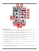
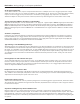
SUM and OR Bus (cont’d)
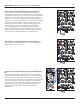
7. CH. 1 Variable Output: The applied signal as processed by CH. 1 controls. Normalized to the SUM and OR busses. Inserting a
patch cable removes the signal from the SUM and OR busses. Output Range +/-10V
8. CH. 2 Variable Output: The applied signal as processed by CH. 2 controls. Normalized to the SUM and OR busses. Inserting a
patch cable removes the signal from the SUM and OR busses. Output Range +/-10V
9. CH. 3 Variable Output: The applied signal as processed by CH. 3 controls. Normalized to the SUM and OR busses. Inserting a
patch cable removes the signal from the SUM and OR busses. Output Range +/-10V
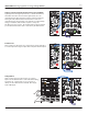
10. CH. 4 Variable Output: The applied signal as processed by CH. 4 controls. Normalized to the SUM and OR busses. Inserting a
patch cable removes the signal from the SUM and OR busses. Output Range +/-10V
11. OR Bus Output: Result of the Analog Logic OR function with respect to the settings of the attenuverter controls for Channels 1,
2, 3, and 4. Range 0V to 10V.
12. SUM Bus Output: Sum of the applied voltages with respect to the settings of the attenuverter controls for Channels 1, 2, 3, and
4. Range +/-10V.
13. Inverted SUM Output: signal from SUM Output turned upside down. Range +/-10V.
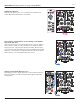
14. SUM Bus LEDs: indicate voltage activity in the SUM bus (and therefore, the Inverted SUM as well). Red LED indicates negative
voltages. Green LED indicates positive voltages.
11