
User manual

1
3
13
2
4
6
8
5
7
9
10
11
12
14 15
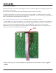
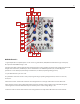
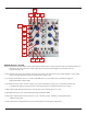
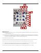
MATHS Channel 1
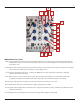
1. Signal Input: Direct Coupled input to circuit. Use for Lag, Portamento, ASR (Attack Sustain Release type envelopes).
Also input to Sum/OR Bus. Range +/-10V
2. Trigger Input: Gate or Pulse applied to this input triggers the circuit regardless of activity at the Signal Input. The result
being a 0V to 10V function, aka Envelope, whose characteristics are dened by the Rise, Fall, and Vari-Response
parameters. Use for Envelope, Pulse Delay, Clock Division, LFO Reset (only during Falling portion).
3. Cycle LED: Indicates Cycle ON or OFF.
4. Cycle Button: Causes the circuit to self cycle, thus generating a repeating voltage function, aka LFO. Use for LFO,
Clock, VCO.
5. Rise Panel Control: Sets the time it takes for the voltage function to ramp up. CW rotation increases Rise Time.
6. Rise CV Input: Linear control signal input for Rise parameter. Positive Control signals increase Rise Time, Negative
control signals decrease Rise Time with respect to the Rise panel control setting. Range +/-8V
7. Fall Panel Control: Sets the time it takes for the voltage function to ramp down. CW rotation increases Fall Time.
6