
Manual

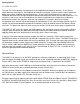

Panel Controls
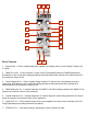
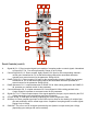
1. Signal IN CH. 1: Direct coupled signal input capable of accepting audio or control signals. Range of up
to 18Vpp.
2. DAMP CV IN CH. 1: Direct coupled, CV input for the corresponding channel’s DAMPing parameter.
Normalized to +8V so that with nothing patched the associated attenuator operates as a manual control for
the parameter. Range 0V-8V.
3. Control Signal IN CH. 1: Direct coupled, highly sensitive CV input for the corresponding channel’s
vactrol gate. Normalized to +8V so that with nothing patched the associated attenuator operates as a
manual control for the parameter. Range 0V-8V.
4. DAMP Attenuator CH. 1: unipolar attenuator for DAMP CV IN. With nothing patched to the DAMP CV IN,
operates as a manual control for the parameter.
5. Control Attenuator CH. 1: unipolar attenuator for Control Signal IN. With nothing patched to the Control
Signal IN, operates as a manual control for the parameter.
6. Signal OUT CH. 1: Direct coupled output of the si gnal applied to the input, as pro-cessed by the LPG.
10Vpp (depending upon settings and source material).
7. STRIKE IN CH. 1: Gate input striking or plucking the vactrol. Expects 8V Gate.
1 2 3
4
6
5
8
7
11
14
15 16
13
12
10
9