Rosie
Limited WARRANTY: Make Noise warrants this product to be free of defects in materials or construction for a period of one year from the date of purchase (proof of purchase/invoice required). Malfunction resulting from wrong power supply voltages, backwards power cable connection, abuse of the product or any other causes determined by Make Noise to be the fault of the user are not covered by this warranty, and normal service rates will apply.
Installation: The Make Noise Rosie is an electronic signal router requiring 30mA of +/- 12V regulated power and a properly formatted distribution receptacle to operate. It is designed to be used within the euro format modular synthesizer system. Go to http://www.doepfer.de/a100_man/a100t_e.htm for the details of this format.
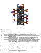
1 5 3 6 2 4 8 7 9 12 10 13 11 Rosie Panel Connections 1. 2. 3. 4. 5. 6. 7. 8. 9. 10. 11. 12. 13. Channel A Signal Input: expects typical 10Vpp Audio signal from Modular System. AC coupled. Channel B Signal Input: expects typical 10Vpp Audio signal from Modular System. AC coupled. Channel A Level Indicator: LED lights to show strength of signal patched to Channel A input. Channel B Level Indicator: LED lights to show strength of signal patched to Channel B input.
Overview Rosie is an output interfacing module with the added functionalities of a FX Loop, Crossfader and Auto-Cue system. It features two Mono Inputs (Channel A and B) each with LED indication of signal strength, a crossfader to select between Channel A and B, a Mono FX Send with Stereo FX Return and Return Level control, a Master Level control with Limiting and overload indication, a Line Level 1/4" Stereo output and the Auto-CUE system with independent Level control and Headphone output.
The Crossfader and Auto Cue System The crossfader is the topmost knob on the Rosie. It allows for manual crossfading between Channel A and B. It works together with the FX Send (FX Loop) and Auto-CUE system. When the crossfader is set to be Full Counter Clock-Wise, Channel A is selected and the signal patched to Channel A signal input will be routed to the FX Send output and Master Line OUT.
The Line Output The LINE out level is clean up to about 75%, where it will start to overload and clip. The OVL (overload) indicator will light to indicate this clipping. The LINE Out is a Tip Ring Sleeve jack the provides a Stereo output on a single jack. It is also OK to use this output as a Mono output by using a Tip Sleeve jack. The LINE out level is clean up to about 75%, where it will start to overload and clip. The OVL (overload) indicator will light to indicate this clipping.
Patch Examples: “DJ” Cueing System Patch two audio signals to ChA and ChB inputs. Choose patch to send to PA with Crossfader, output Master Line OUT to PA. Monitor Cue Output with headphones to audition the other patch. When ready, use Crossfader to switch to the other patch in the PA. Two-input mixer Patch two audio sources to ChA and ChB Inputs. Set mix with Crossfader. Take output from Master Line OUT.