
Manual

Source Cables
These are cables where one end of the cable is patched to the output of a signal generator/ processor in the
modular system and the other end is not patched. The tip of the Source cable is touched to the surface of
the TELEPLEXER at the location and time of the desired patch connection. When the tip of the source cable
is removed from the surface of the TELEPLEXER, the patch connection is broken and ended. Possible
sources include LFO, Envelope, Sequence, Random Voltage, Clock, Gate, Pulse, Audio Signals and more.
As long as the signal is generated within the modular system in which the TELEPLEXER is installed, it is OK
to use. It is not OK to use signals from outside the modular system where the TELEPLEXER is installed.
Auxiliary Ins
We included one unity gain Aux IN per channel on the TELEPLEXER. These inputs are useful when you
have a signal source that you would like to run continuously to the destination or where you would like to
control the signal level/routing elsewhere in the patch using a VCA or Voltage Control Switch, for example.
The plates allow you to add (using the non-inverting plates) or subtract (using the inverting plates) signals
from the signal patched to the Aux IN.
For example, you might want to sequence the FOLD parameter, and then add and subtract 2 different LFOs
from the sequence. To do this, you would patch the Sequence to the Aux IN, the OUT to the FOLD CV IN,
and the patch Source Cables to CH. 1 and CH. 4 of MATHS programmed for some type of LFO. Using the
attenuvertors on MATHS, you could set the desired modulation depth while using the TELEPLEXER to
momentarily add or subtract the LFOs from the sequence.
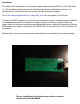
OUTs
The outputs of the TELEPLXER are to be patched to your desired destinations. Each of the 3 outputs is
capable of driving multiple destinations, so buffered multiple is not needed. Each output has LED indication
of channel number (1, 2 or 3), signal polarity (Green is Positive, Red is Negative) and signal level (stronger
signals are brighter). Just about any input within the modular system will work as a destination. It is possible
to route Control Voltages (LFOs, Envelopes, Sequences, Random Voltages), Audio Signals (VCO Waveform
outputs, signal processor outputs), and Timing signals (Clocks, Gates, Pulses); however, it is generally not
desirable to mix these signals. For example, an audio signal will not be useful when patched to a timing
destination. Therefore, it is a good idea to teleplex control voltages OR timing events OR audio signals.
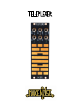
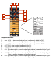
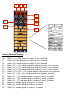
The PLATES
The metal plates on the face of the TELEPLEXER are how the user communicates with the module.
Touching the tip of a Source Cable to these plates allows user to create connections in a patch. The result is
everything from momentary modulations to sustained timbral shifts to complete jumbling of signal path. It is
possible to use as many sources as desired- only your available patch cables will be the limit. Sources
should only come from within the system where the TELEPLEXER is installed.
The 14 plates cover every possible combination of signal routing to the 3 outputs. Inverted routes are
included as well, making it possible to both add & subtract voltages by using several sources at multiple
plates. For example, touch Source Cable 1 to Plate (+1) and Source Cable 2 to Plate (-1) and you will be
subtracting these to signals with the result appearing at OUT 1. If you were to touch Source Cable 1 to Plate
(+1) + (+2) and Source Cable 2 to Plate (+2), you will be adding these to signals- the result appearing at
OUT 2. Additionally, Source Cable 1 would appear at OUT 1.