
User manual
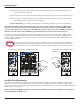
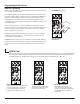
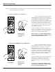
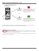
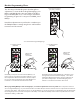
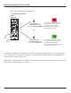


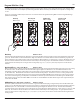
Table Of Contents

11
There are four ways to determine the Leading Tempo, which synchronize the (6) Variable Clock Outputs of the TEMPI:
1. With nothing patched to the Leading Tempo Input, the last-Stored Tempo is used (refer to Bank Edit Page’s Store
Function, described on page 24).
2. When an External Clock is patched to the Leading Tempo Input, the External Clock source is followed after 2 pulses.
3. When an internally-connected bus line is used via the Tempo Bus, the generated Clock signal is Followed (refer to
Bank Edit Page’s Follow Setting, described on page 26).
4. New to v31 rmware: if Tap Tempo is enabled on the Clock Edit Page, tap Button-1 to set the Leading Tempo.
Leading Tempo
Variable Clock Programming:
To Program the Leading Tempo externally via tapping:
Note: While externally clocking, when changing Tempo from fast to slow, there will be some delay, as TEMPI needs a
minimum of 2 Clock pulses to measure the incoming Clock rate and lock into sync. If synchronizing TEMPI to a DAW
project, include 2 bars of silence, with sync clock running at the beginning of the composition so TEMPI locks into sync
when the composition starts. Also, for DAW Sync, try Run/Stop All (James Cigler mode) described on Page 20.
It is possible to tap the Leading Tempo by patching a Gate Output, for example, from the Pressure Points, to TEMPI’s Tempo
Input and tapping the desired Tempo on the Pressure Points. Remember: at least (2) taps are required. The TEMPI will lock on
to the new Tempo and Follow until a new Tempo is tapped. The Tempo is indicated by the Blue Tempo LED that ashes just
below the TEMPO Input jack.
It is also possible to use Channel 1 as the Leading Tap Tempo. To do this, rst migrate to the Clock Edit Page
by double pressing PGM_A and PGM_B. Then, press Channel Button-1 until it turns Purple to turn enable
Leading Tap Tempo. Once the Leading Tempo is set, you may program Variable Clocks again with Channel-1.
The Variable Clock Outputs may be Machine Programmed by pressing and holding a combination of PGM_A or PGM_B and/or
Button(s)1-6 for the associated Channel Outputs. Each of the Variable Clock Outputs are Multiples or Divisions of the Leading
Tempo. When Variable Clock Outputs are Active (Mute Disabled) and/or Mod Disabled, the associated Channel Button LED(s) ash
Blue to indicate Clock High/Low.
NOTE: The default Pulse Width of the Variable Clock Outputs is 50% Duty Cycle. This can be changed to 10ms Triggers via
the Clock Edit Page, per rmware v.31.
Programming with Leading Tap Tempo
(rmware v.31)
New to v.31