Content 1 The components........................................................................... 3 2 The first LED lamp........................................................................4 3 More light!.................................................................................... 7 4 Switchable brightness................................................................ 10 5 series connection with two LEDs................................................13 6 Parallel connection....................
22 An automatic colour-changing LED...........................................41 23 White flashing light .................................................................44 24 Green flashing light..................................................................45 25 Flickering and flashing with six LEDs.......................................
1 The components This package contains exciting projects with LEDs and other electronic components. In addition, there are info boxes all around that explain why the experiments work the way they do. Of course, you can also just perform the actual experiments.
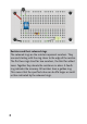
exactly the right contact sockets of the plug-in board. You should first prick small holes in the protective foil at the back of the board using a needle and insert the cables from below. This way, they will no longer easily slip. The switch and fuse should be placed exactly in the position shown. This applies to all other experiments. This will prevent big mistakes from occurring.
which holes of the plug-in board, the components have to be plugged. Fit the components onto the plug-in board using small flatnose pliers. Carefully insert the wires from the top. The correct position of the connections is important. When installing LEDs, it is important to note the mounting direction. The shorter wire is the negative pole (the cathode K); the longer wire is the positive pole (the anode A). The larger holder for the LED crystal is visible from the cathode side.
The resistor may be installed in any direction. It is marked by coloured rings (yellow, violet, red and gold), which represent a numerical value. In this case, the rings indicate that the resistance is 4700 ohms (4700 Ω). The battery clip should only be plugged into the battery when everything has been set up and properly checked. Then you shift switch 1 to the ON position. The LED should now shine white. If it does not work, the LED may have been installed the wrong way around.
and the LED contains an arrow showing the current direction. Two small arrows represent the generated light. Here you’ll see all components form a complete path, i.e. a closed circuit. Only at one point is the circuit interrupted: where the switch has just opened. 3 More light! The LED was not very bright in the first experiment. Here another resistor is installed. The first resistance was 4.7k Ω (4,700 ohms, yellow, violet, red), this has only 0.47k Ω (470 Ohm, yellow, purple, brown).
Resistors and their coloured rings The coloured rings on the resistors represent numbers. They are read starting with the ring closer to the edge of the resistor. The first two rings stand for two numbers, the third for added zeros. Together they denote the resistance in ohms. A fourth ring indicates the accuracy. All resistors have a golden ring. This means that the specified value can be 5% larger or smaller than indicated by the coloured rings.
The resistor colour code Colour Ring 1 1. Code Ring 2 2. Code 0 Ring 3 Multiplier 1 Ring 4 Tolerance Brown Red Orange 1 2 3 1 2 3 10 100 1000 1% 2% Yellow 4 4 10000 Green Blue 5 6 5 6 100000 1000000 Purple 7 7 10000000 Grey 8 8 White 9 9 Black 0.5 % Gold 0.1 5% Silver 0.
4 Switchable brightness More brightness is sometimes an advantage, but also has a disadvantage. It makes the battery is run down faster. It is more practical if you can choose whether you need a lot of light or just a little. That’s where the second switch comes in, which is connected via a cable to two thin connectors. When in the ON position, more current flows through and the LED shines brighter. Switch 1 is for when you require less brightness.
Actually, there are three brightness levels. Switch 1 is for simple brightness and switch 2 for tenfold brightness. But if both switches are on, the result is eleven times the brightness. You can easily test it: Turn on switch 2 and turn switch 1 on and off alternately. The difference is, however, very insignificant and hardly recognisable. Voltage, resistance and current As is known, the electrical voltage is measured in volts (V). The battery is 9 V.
Using a suitable meter, you could measure how much current flows through the LED. But you can also work out how strong the voltage, at the moment, the battery is and what the voltage is at the LED. If the battery is still new, it will have a voltage of 9 V. The LED needs about 3 V, which leaves another 6 V for the resistor. You can calculate the low brightness like this: Current = voltage/resistance Current = 6 V/4700 Ω Current = 0.0013 A = 1.3 mA That’s not very much, only 1.
5 series connection with two LEDs Here we use a second white LED in the circuit. The light will be a little brighter. The brightness is enough to read at night. And once again, there are two brightness levels. Depending on the situation, you can decide how much light is needed. Series connection In series connection, the same current flows through two or more consumers. It is an “unbranched circuit” because there is only one way the current can flow. This means that the current is the same at each point.
Simplified circuit diagram of a series connection The voltage is divided among the consumers in the circuit. In this case, there are two LEDs and a resistor. Each white LED needs about 3V. So, two LEDs have a voltage drop of 6V. And because the battery has 9V, there is a 3V voltage drop across the resistor. In this case, therefore, the battery voltage is divided equally between three consumers. The same applies to the energy consumption.
Parallel connection The parallel connection is also called “branched circuit”. The current through the resistor is divided by two LEDs. Half the current flows through one LED, the other half through the other LED. A small test can prove this: If you remove the cable between both LEDs, one LED goes out, but the other one shines brighter. All the current then flows through that LED.
Parallel connection with two LEDs 7 Flashing Morse code device A push button switches the signal LED on and off in this experiment. This creates a simple Morse code device. The signal LED uses high brightness. In addition, there is a LED with lower steady light, which can be switched on via switch 1.
Info Morse code 17
8 Green signals Here, a green LED is installed instead of the white signal LED. The light of this LED can be seen over even greater distances. This allows you to exchange messages with friends who are in sight.
9 An electric tester In this experiment, a test device is built to check which things conduct electricity. The resistance of 10k Ω (brown, black, orange) should further reduce the current through the LED, as great brightness is not required here. There are two cables with test tips. You can use these to touch any object. When the LED lights up, you know that electricity is flowing through it. All metals conduct electricity, but also other things such as pencil lead. Even weak conductors are detected.
20
Additional experiment The test device is also suitable for testing electrical components. The resistors in the package conduct the current to different degrees. An LED will only conduct in one direction. And you can check if a light bulb is still working or has already burned out. 10 red and green light The aim of this experiment is to compare the brightness of different coloured LEDs. A red LED should be connected in series to the green LED.
22
11 A colour switcher With a resistance of 2.2k Ω (red, red, red) and two LEDs, a very special circuit is built – a green-red switch. Every time you press the button, the red LED goes on, but the green LED goes off. When the switch contact is closed, it is actually a normal parallel connection like in Experiment 6. But in that experiment similar LEDs were used; this time they are different. The green LED needs a higher voltage than the red LED.
The PTC fuse All experiments use a fuse that kicks in when an error occurs. If you accidentally cause a short circuit, a wire could become red hot, or the battery could overheat and in the worst case even explode. But the fuse can prevent this from happening. Many fuses burn out easily when a short circuit occurs. But this special fuse is different. It is a self-resetting fuse called PTC fuse.
rent to pass through, as its resistance rises sharply. Hence the name. PTC stands for “Positive Temperature Coefficient” and means that the resistance increases as the temperature rises. At a voltage of 9 V, a temperature of about 60 degrees is reached. If you turn off the power and eliminate the error, the fuse cools down and works like new again. 12 A yellow-green switch This time, the colour switch must be tested with a yellow LED. You can use them just like for the other colours.
13 Adjustable brightness The potentiometer (pot for short) is a three-terminal adjustable resistor. Such components are also used as volume controls in radios. But in this case, it is used to set the brightness of a green LED. The further you turn the knob to the right, the brighter the LED will shine. So far, different resistances between 0.47k Ω and 10k Ω have been used. The pot can be set between 0k Ω and 10k Ω.
The opened pot 27
14 red – green – white Another cable can be used to connect the third port of the potentiometer. This allows you to adjust the electrical voltage in the circuit. There are three LEDs connected to the slider of the potentiometer. The red and green LEDs have their own series resistor. Although the white LED is connected directly, at full brightness, the resistance is 470 Ω. If you turn the knob all the way to the left, all LEDs go out.
Additional studies: Spectral colours A CD can be used as a mirror to look at the three LEDs. By changing the angle to the correct position, the white LED will be visible as stripes in all colours of the rainbow. The light spectrum is pulled apart because the CD has narrow lines that cause interference of the light waves. The lines of the red and green LEDs are also pulled apart slightly, but contain only a small part of the light spectrum. The white LED is actually a blue LED.
15 Setting from green to red In this experiment, we create an LED with adjustable colour. It shines either red or green or in both colours. With the potentiometer you can adjust the brightness of both LEDs. If the green LED shines brighter when turning to the left, the red LED will shine dimmer. And if you turn the potentiometer more to the right, the red LED will shine brighter while the green LED will be dimmer.
the potentiometer and all intermediate tones in the range red – yellow – green. 16 Automatic flashing light The red flashing LED is a special LED with additional internal electronics.
resistor, it turns on and off again and again. For comparison, the red LED with adjustable brightness should be placed next to it.
The flashing LED The flashing LED contains a transistor as an electronic switch. In addition, other transistors and other components are required, which together form a complex circuit and control the exact timing. Everything is constructed on a small piece of silicon, which is installed next to the LED crystal. 17 flashing lights – red and green Now the flashing lights should be extended so that two LEDs flash at the same time. For this, the green LED is switched in series to the red flashing LED.
The principle of series connection 18 alternating flash lights How the changing colours work, has already been tested in Experiment 11. But there a push-button was used to turn on a red LED. This time it is the automatic switch built into the flashing LED, the LED controller. Here, the flashing red LED and the green LED are connected in parallel.
green LED needs more voltage than a red LED, it only lights up during the pauses. In addition, the LED with the colour pink is now used. It should first be tested with adjustable brightness. If you swap the green and the pink LEDs, the pink LED will flash and the green will show even brightness with adjustable brightness. This proves that even a pink LED needs more voltage than a red LED.
Structure of the pink LED The pink LED is similar to the white LED. The actual LED crystal emits blue light. But it is covered with a fluorescent material that captures part of the blue light and emits it as red light. So, it happens that the pink LED actually has two colours: red and blue. Looking at a CD reveals this ...
19 One change indicator with four LEDs Now we’re building flasher with four colours. A yellow LED is in series with the flashing LED and therefore flashes in the same cycle. Parallel to this is a series connection of a green and a pink LED. These two LEDs require more power and shine whenever red and yellow are off.
Additional experiments: Different series resistors are tested in the circuit. The smaller the resistance, the greater the brightness. But does the switch still work with the slightest resistance? 20 Alarm system with flashing indicator You can build a simple alarm system with two LEDs. The green LED lights up permanently, the red one not at first, because the cable short-circuits it. Green means: Everything’s ok! You can tie a piece of string to the cable and attach it to the door.
21 A game of skill For this game you have to try to press the button exactly in time with the flashing red LED. If you press the button, the green LED remains off. When you let go, it flashes at the same rate as the flashing red LED.
small amount of current to flow. This is important because in this game you have to look closely at the LEDs, but not be dazzled. The button must be pressed again and again only releasing it briefly released once the flashing LED goes out. If you miss the point in time, the green LED will flash.
Bridge circuit A bridge circuit consists of two series connections and one component between the two. On the left, the series connection contains a resistor and the flashing LED. On the right, there is a resistor and a switch. An LED is located between the resistor and switch forming the bridge. The question arises: Is the tension higher on the left or on the right? The green LED can only shine once the flashing LED on the left is shining and the switch on the right is off.
Caution: Never look directly into the LED when it is switched on. The blue light especially can damage the retina. Because the eye is less sensitive to blue light, the blue LED appears less bright, but is still very dangerous to the eyes. The colour-changing LED is operated in this experiment using adjustable brightness. You can try another experiment. The potentiometer is connected as a voltage divider, so that even very small voltages from as low as 0 V can be set.
43
Pulse width modulation The individual LEDs are not only switched on and off, but also appear lighter or darker. Sometimes the brightness increases evenly. Therefore, you might suspect that some kind of potentiometer is installed to change the current. But, actually the LEDs are turned on and off in quick succession. If you move the entire structure back and forth quickly, you can see light strokes of different lengths. The length of the pulses is changed and therefore the average duty cycle.
24 Green flashing light This time, the green LED should light up in the opposite direction of the colour-changing LED. It must be connected in parallel. The suitable resistance is 1.5k Ω (brown, green, red). Whenever the colour change controller turns on the red LED, the green LED goes off.
of the green LED. And you can sometimes even see seamless changes in brightness in the green LED. Additional experiment One can test many different resistances between 470 Ω and 22k Ω in this circuit. This makes it possible to set many different brightness levels. The goal may be more brightness (lower resistance) or longer battery life (greater resistance).
25 Flickering and flashing with six LEDs With a total of six LEDs and two identical resistors of 1k Ω (brown, black, red), we are going to create a colourful and varied LED light at the end, in which all LEDs flash or flicker. Actually, the package contains only two LEDs with a built-in controller. But there are some circuit tricks with which other LEDs can blink or flicker. The circuit consists of two LED series circuits and a bridge circuit with two oppositely poled LEDs.
Six LEDs are now installed, but two white LEDs have no assigned purpose yet. It can be fun to add them. There are many different possibilities. Suggestions lead to the presented experiments. Overall, countless new circuits can be developed using existing components.
Imprint Dear Customers, This product has been manufactured in accordance with the applicable European directives and therefore bears the CE mark. The intended use is described in the enclosed instructions. For any other use or modification of the product, you are responsible to comply with applicable rules. Therefore, install the circuits exactly as described in the instructions. The product may only be distributed along with this manual.