
User manual


6
The resistor may be installed in any direction. It is marked by
coloured rings (yellow, violet, red and gold), which represent
a numerical value. In this case, the rings indicate that the
resistance is 4700 ohms (4700 Ω).
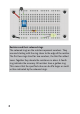
The battery clip should only be plugged into the battery when
everything has been set up and properly checked. Then you
shift switch 1 to the ON position. The LED should now shine
white. If it does not work, the LED may have been installed
the wrong way around. You should also check all other con-
nections and compare everything exactly with the drawing.
Attention!
You absolutely must avoid short circuiting the battery, as it will
result in a current of several amperes. The battery will then
quickly become unusable. In extreme cases, it could even ex-
plode, or wires could become red hot.
Diagrams
A circuit diagram portray the connections of the components
in a simplified form. In the beginning, it may seem a bit con-
fusing because the real components look different. But once
you get used to it, a diagram will clarify how everything fits
together.
The battery consists of six 1.5 V battery cells. The long dash
indicates the positive pole. The fuse is indicated as a box
with a wire. The switch indicates an open connection, so it is
currently in the off position. The resistor is displayed as a box