Quick-Start Guide V1.0.16 Dec.
Contents SAFETY INSTRUCTIONS ........................................................................................................................................................ 3 PRODUCT OVERVIEW ........................................................................................................................................................... 4 1.REFERENCE FRAME .......................................................................................................................................
Safety Instructions 1. Please don’t put your hands between the arms when uArm is moving. 2. Please use the official power supply for safety reasons. 3. Please clear a space for uArm, in case of knocking down anything.
Product Overview 1.
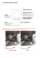
2. Buttons & Indicator Lights Caution: By default, the user defined button is for switching between Bluetooth and USB mode. Please ensure the button is UP while communicating with uArm via USB.
3.
Hardware Installation 1. Suction Cup (Default) Preparation Step 1: Install the suction to the end-effector and lock the nut tightly Note: Similarly, if you want to uninstall suction cup, unlock the nut.
/ 50
2.
(Please pay attention to the direction) Caution: If the laser could not engrave the paper, please open the uarm studio and start the laser engraving, then focus adjust the lens of laser slowly. Please do not touch the light of laser during the engraving.
3. 3D Printing Step 1: Install the 3D printing extruder and locked the nut tightly Step 2: Install the 3D printing feeding system Caution: Please ensure the connection is correct. Or the computer wont recognize the uarm.
(Feed the PLA material we offered into the feeding system) Step 3: Install the PTFE tube Feeding the filament Installing the tube 12 / 50
Step 4: Keep feeding the material until it’s 60mm out of the other side of PTFE tube. 60mm Caution: Sometimes the filament can’t be extruded, that might be caused by the top of filament. If the tip is deformed during the cutting off, the filament won’t go through the heat end successfully.
Step 6: Stick the masking tape on the table Caution: someone might get trouble with the not horizontal, please try to calibrate the arm following this link .
4. Swift Gripper Preparation Step 1: Unscrew suction cup with the hex bar wrench.
Step 2: Fix the gripper and lock the nut tightly Step 3: Plug the 4th axis motor and gripper 16 / 50
5. Swift Universal Holder Preparation Step 1 : Unscrew suction cup with the hex bar wrench.
Step 2: Fix the gripper and lock the nut tightly Step 3: Plug in the 4th axis motor 18 / 50
6. Seeed Grove Modules Seeed Grove modules is a series of different sensors which helps us to extend the function of uArm to a completely new level. We are offering two parts to help you to connect the uArm with Grove much more easily. Grove Extension Grove mounting block Caution: Grove extension for the uArm end-effector is just designed for(Step 1,2) PIR Motion Sensor Mini Fan Module Electromagnet Module Ultrasonic Ranger Other Digital or Analog modules.
Step 1 : Plug in the Grove breakout and fix the grove module to the mounting block. Step 2 : Wiring.
Step 3 : For the IIC modules 21 / 50
7. OpenMV Module(the firmware should be 3.1.9 or later) Preparation Step 1 : Download the latest OpenMV IDE Click here (Download the latest OpenMV IDE from: https://openmv.
Step 2 : Upgrade the latest firmware to OpenMV by OpenMV IDE Click here Step 3 : Run the helloworld.py and focus the lens in the right window Click here Note: After IDE get the video, then rotate the lens to finish focusing(to see the objects 20cm away) then tight the screw.
Step 4 : Get the tracking.py code and save it to the OpenMV You could find the tracking.py from: https://github.com/uArm-Developer/OpenMV-Examples Note: The file system of OpenMV 2.4.1 is not very stable, and make sure the file has been stored into the module. Here is our steps: (1) Open the disk of OpenMV, and drag the tracking.py file into the disk and renamed it main.py; (2) If the code has been stored successfully, power on the module, the blue light turns on.
Caution: Please ensure the connection is correct. Or the computer wont recognize the uarm. Step 6 : Install the camera module to the end-effector Note: Please pay attention to the assembling direction of OpenMV, or the arm will move to the opposite direction. And make sure the OpenMV is disconnected with you PC or the IDE will control the OpenMV.
Step 7 : Keep the table clean and non-reflective and get something with a lot of details like a pcb with resistors Step 8 : Put the object in front of uArm Swift Pro about 25cm away 26 / 50
Step 9 : Connect the USB port and power port of uArm, press the power button and open a serial monitor (for example Arduino IDE). Step 10 : Adjust the settings (newline & 115200 baud) and then send the M2500 command which will switch the main UART port from USB to the port of OpenMV. Step 11 : Move the object slowly, and the arm will follow it.
Offline Learning Mode Use buttons on the base to “teach” uArm by hand.
Teach: 1. Start learning mode. Press the once, and the status indicator truns green. 2. Teach the robot manually. Press the effector, again to turn off. (If once to turn on the end- is down end-effector is gripper, or it is pump. Please remember to keep the button up after learning or it will turn on the Bluetooth. Page 5) 3. Finish the learning process. Press once, and the status indicator turns off. PLAY: 1. One-time playback: Press once, or Loop playback: press hold for 2 seconds. 2.
Software: uArm Studio (Win/Mac) 1.Download uArm Studio from: http://www.ufactory.cc/#/en/support/ * Windows(Win7/8 or before) users will be reminded to install driver. Simply follow the instructions to install. 2.Device Connection 1)Plug in the power cable. 2)Press down the power button. 3)Connect uArm to your computer via USB. Status of device connection is displayed on home page. More info is displayed in “Setting”.
3.Drawing/Laser Engraving 1) Design a pattern. Insert text/shape Insert an image (“outline” or “black & white”.) 2) Click the play button to continue.
⚠️ IMPORTANT: Please adjust zero point before drawing/engraving. Ensure the pen/laser is TOUCHING the platform. For laser engraving, you can also adjust the speed of engraving. 4) Start drawing/engraving! 4.3D Printing Preparation 1) Download CuraForuArm 2) Double-click .dmg/.exe file to install. 3) Enter the 3D Printing section in Studio, and CuraForuArm window will pop up automatically. If not, click the “Open Cura” button.
1) Import an .stl file, edit the size/position of the model. 2) Select “uArm Swift Pro” as the printer, and choose the related profile. It is recommended to keep the default settings unchanged. When setting the parameters of printer please choose the print setup option(orange rectangle), if you choose the printer monitor option(the right button) you can hardly find the printer. 3) Open Printer Monitor. IMPORTANT: Please adjust zero point before printing. Ensure the hot end is JUST TOUCHING the platform.
Then click “Save Zero”. (The zero point of each arm is not the same, please adjust the zero point following the step 3) before printing.) 4) Start printing! The 3D extruder will automatically heat up to 200℃ to print. uArm will remain still during the pre-heating section. Please don’t touch the metal part of the extruder for safety reason.
5.Teach & Play: Learning Mode What is Teach & Play? Teach uArm by hand, and then replay the recording anytime. How? 1) Make a recording • Click the “New Recording” button to start “teaching”, OR, • Use the buttons on the base (usage of the buttons is the same as that under “Offline Learning Mode”).
3) Replay the recording in different speed and times What makes “Teach & Play” different from “Offline Learning Mode”? 1) No time limit while “teaching” with uArm Studio. 2) You may save, export your recordings and import recordings made by others. 3) You may apply your recording in Blockly (visual programming interface, which is explained up next).
6.Blockly: Visual Programming What is Blockly? Blockly in uArm Studio is a visual programming interface specially designed for controlling uArm. Getting Started Three “missions” are prepared to get you through Blockly quickly. Please try them out! What can you do with Blockly? 1) Control uArm’s basic movements 2) Change events (i.e.
3) Apply recorded movements 4) Dig deeper into programming (functions, variables, etc.
For Developers 1.Communication Protocol 1) Introduction: • uArm gCode is an important part of the uArm software. • Based on the standard gCode protocol, we add a new protocol head in front of the gCode so that it can be more easily to use and debug. • What’s more, it is designed to be compatible with the standard gCode.
• And the data following the symbol decided by the PC, and the reply from the uArm should have the same data which indicates it finish the command. (In the example above, PC sends the command with ‘#25’ and uArm replies the command with ’$25’) Command without the underline: it’s the standard gCode. Caution 1.There should be blank space between each parameter; 2.
GCode Command (v1.2) Description Feedback 1. #n is used for the debug, if you don’t want to use it please remove it directly. (For Example: G2202 N0 V90\n) 2. ‘\n’ is the symbol of line feed. Moving Command (parameters are in underline) #n G0 X100 Y100 Z100 F1000\n Move to XYZ(mm), F is speed(mm/min) $n ok \n or $n Ex \n (refer to Err output) #n G1 X100 Y100 Z100 F1000\n After entering the laser mode $n ok \n or $n Ex \n (refer to Err (M2400 S1), command G1 output) means laser on, G0 means off.
#n M2201 N0\n attach motor, N is ID of joints(0~3) $n ok \n or $n Ex \n (refer to Err output) #n M2202 N0\n Detach motor, N is ID of joints(0~3) $n ok \n or $n Ex \n (refer to Err output) #n M2203 N0\n Check if the motor is attached, N is ID of joints(0~3) $n ok V1\n (1 attached,0 detached) #n M2210 F1000 T200\n buzzer,F is frequency, T is time (ms) $n ok \n or $n Ex \n (refer to Err output) #n M2211 N0 A200 T1\n Read EEPROM N(0~2,0 is internal EEPROM,1 is USR_E2PROM, 2 is SYS_E2PROM), A is add
#n M2245 Vbtname\n Set the name of Bluetooth, 11 letters limited #n M2304 P0\n Please check the Grove modules below #n M2305 P0 N1\n Please check the Grove modules below #n M2306 P0 V1000\n Please check the Grove modules below #n M2307 P0 V1\n Please check the Grove modules below #n M2400 S0\n Set the mode of arm (0:Normal 1:Laser 2:3D printing 3:Universal holder) $n ok \n #n M2401\n Set the current position into the reference position $n ok \n #n M2410\n Set the height zero point $n ok \n
#n P2231\n Get the status of pump $n ok V1\n (0 stop, 1 working, 2 grabbing things) #n P2232\n Get the status of gripper $n ok V1\n (0 stop, 1 working, 2 grabbing things) #n P2233\n Get the status of limited switch $n ok V1 (1 triggered, 0 untriggered) #n P2234\n Get the status of power connection $n ok V1 (1 connected, 0 unconnected) #n P2240 N1\n Get the status of digital IO $n ok V1\n (1 High, 0 Low) #n P2241 N1\n Get the status of analog IO $n ok V295\n (return the data of ADC) #n P224
E25 Operation failure Grove modules Grove Num 1 2 3 4 5 6 7 Module Chainable LED RGB Button Slide Potentiometer Vibration Motor Light Sensor Angle Sensor Air Sensor Quality Commands Description Support Ports Return #n M2304 P3\n Deinit 3, 4, 5 $n ok\n #n M2305 P3 N1 V2\n Init Module 1 in Port 3. V is the number of LEDs chained.
8 Sound Sensor #n M2306 P1 V1000\n Set report interval (ms) 1, 2 @11 P1 N7 V583\n #n M2304 P1\n Deinit 1, 2 $n ok \n #n M2305 P1 N8\n Init Module 8 in Port 1 1, 2 $n ok \n #n M2306 P1 V1000\n Set report interval (ms) 1, 2 @11 P1 N8 V583\n #n M2304 P0\n Deinit 0 $n ok \n #n M2305 P0 N9\n Init Module 9 in Port 0 0 $n ok \n 0 @11 P0 N9 X2.0 Y2.0 Z2.0 H2.0 T2.0\n Set report interval (ms) 9 XYZ is the acceleration of each axis.
13 14 15 16 Fan Electromagnet Temperature Humidity & #n M2304 P4\n Deinit 4, 8, 9 $n ok \n #n M2305 P4 N13\n Init Module 13 in Port 4 4, 8, 9 $n ok \n #n M2307 P4 V120\n Set Fan speed(0~255) 4, 8, 9 $n ok \n #n M2304 P3\n Deinit 3, 4, 5, 8, 9 $n ok \n #n M2305 P3 N14\n Init Module 14 in Port 3 3, 4, 5, 8, 9 $n ok \n #n M2307 P3 V1\n 1:turn on 0: turn off 3, 4, 5, 8, 9 $n ok \n #n M2304 P0\n Deinit 0 $n ok \n #n M2305 P0 N15\n Init Module 15 in Port 0 0 $n ok \n #n M23
19 Infrared Reflective Sensor #n M2304 P3\n Deinit 3, 4, 5, 8, 9 $n ok \n #n M2305 P3 N19\n Init Module 19 in Port 3 3, 4, 5, 8, 9 $n ok \n @11 P3 N19 V1\n #n M2306 P3 V1000\n 20 EMG Detector Set report interval (ms) 3, 4, 5, 8, 9 1: object detected 0: no detected #n M2304 P1\n Deinit 1, 2 $n ok \n #n M2305 P1 N20\n Init Module 20 in Port 1 1, 2 $n ok \n #n M2306 P1 V1000\n Set report interval (ms) 1, 2 @11 P1 V583\n object N20 d.
uArm Community UFACTORY Official Forum uArm User Facebook Group 49 / 50
Release Note Version 1.0.7 1.0.8 1.0.9 1.0.10 1.0.11 1.0.12 1.0.13 1.0.14 1.0.15 1.0.