
Instructions


4
exactly the right contact sockets of the plug-in board. You
should first prick small holes in the protective foil at the back
of the board using a needle and insert the cables from below.
This way, they will no longer easily slip. The switch and fuse
should be placed exactly in the position shown. This applies
to all other experiments. This will prevent big mistakes from
occurring.
There are also seven light emitting diodes (LEDs), including
five colourful red, yellow, green, blue, and pink LEDs, a red
flashing LED that has a clearer casing to recognise it, an extra
small chip, and a red LED automatic colour-changing LED in
a clear housing.
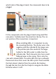
Caution: The LEDs must never be connected directly to a 9 V
battery! You must always use a resistor to reduce the electri-
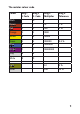
cal current. There are twelve different resistances, which can
be distinguished by their coloured rings.
A push button and an adjustable resistor (potentiometer)
provide even more variety in the experiments. With these you
can turn on the power or adjust the brightness of an LED.
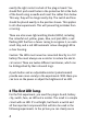
2 The first LED lamp
For the first experiment, you need the plug-in board, battery
clip, switch, fuse, an LED and a resistor. The result is a simple
circuit with an LED. It’s not bright, but there’s a switch and
all the important components that will also be used in the
following experiments. In the picture you can clearly see in