
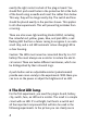
Instructions


7
and the LED contains an arrow showing the current direction.
Two small arrows represent the generated light.
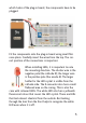
Here you’ll see all components form a complete path, i.e. a
closed circuit. Only at one point is the circuit interrupted:
where the switch has just opened.
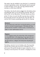
3 More light!
The LED was not very bright in the first experiment. Here
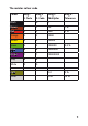
another resistor is installed. The first resistance was 4.7k
Ω (4,700 ohms, yellow, violet, red), this has only 0.47k Ω
(470Ohm, yellow, purple, brown). It therefore allows signifi-
cantly more current through. This makes the LED shine much
brighter.