Contenuto 1 I componenti................................................................................. 3 2 La prima luce a LED.....................................................................4 3 Più luce!........................................................................................ 7 4 Luminosità commutabile........................................................... 10 5 Collegamento in serie con due LED............................................13 6 Collegato in parallelo.................
22 Un LED di cambio colore automatico.......................................41 23 Luce bianca tremolante ...........................................................44 24 Luce verde intermittente...........................................................45 25 Luce lampeggiante e tremolante con sei LED..........................
1 I componenti Questo pacchetto si occupa di progetti divertenti con diodi emettitori di luce e altri componenti elettronici. Inoltre, ci sono caselle informative che spiegano perché gli esperimenti funzionano e come funzionano. Naturalmente, è anche possibile effettuare i test da soli.
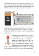
successivi. Le estremità scoperte dei cavi rossi e neri devono essere inserite esattamente nei fori di contatto corretti della scheda. Per prima cosa si dovrebbero creare dei piccoli fori nella pellicola protettiva sul retro della piastra con un ago e inserire i cavi dal basso. Questo impedirà che essi scivolino facilmente. L’interruttore e il fusibile devono essere inseriti esattamente nella posizione indicata.
particolarmente luminosa, un interruttore è disponibile per tutte le parti importanti, che vengono utilizzate anche nei seguenti esperimenti. L’immagine mostra esattamente in quali fori della bacheca devono essere inseriti i componenti. Una piccola pinza a punta piatta è adatta per il posizionamento dei componenti sulla bacheca. I fili vanno inseriti esattamente dall’alto. La posizione corretta dei collegamenti è importante. Il LED deve essere installato nella direzione corretta.
simili dall’esterno. Guardare attraverso l’obiettivo dalla parte anteriore aiuta sempre a riconoscere il LED bianco anche quando è spento. La resistenza può essere installata in qualsiasi direzione. Trasporta anelli di colore (giallo, viola, rosso e oro), che rappresentano un valore numerico. In questo caso, gli anelli indicano che la resistenza è di 4.700 Ohm (4.700 Ω). La clip della batteria non deve essere inserita nella stessa prima dell’assemblaggio e il relativo controllo.
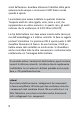
La batteria è composta da sei celle da 1,5 V. La linea più lunga indica il polo positivo. Il fusibile è disegnato come una scatola con un filo. L’interruttore mostra una connessione aperta, in posizione Off. La resistenza viene visualizzata come una scatola e il LED contiene una freccia che indica la direzione della corrente. Due frecce piccole rappresentano la luce generata. In questo caso si può notare che tutti i componenti formano un percorso completo, un circuito chiuso.
Ohm, giallo, viola, marrone). In questo modo la corrente aumenta notevolmente. Ciò rende il LED molto più luminoso. Resistenze e loro anelli di colore Gli anelli colorati sulle resistenze rappresentano dei numeri. Si leggono a partire dall’anello più vicino al bordo della resistenza. I primi due anelli stanno per due cifre, il terzo per zeri aggiunti. Insieme indicano la resistenza in ohm. Un quarto anello indica la precisione. Tutti i resistori hanno un anello dorato.
Il codice colore resistenza colorazione Anello 1 1ª cifra Nero Anello 2 Anello 3 2ª cifra Moltiplicatore 0 1 Anello 4 Tolleranza Marrone Rosso Arancione 1 2 3 1 2 3 10 100 1000 1% 2% Giallo 4 4 10000 Verde Azzurro 5 6 5 6 100000 1000000 Viola 7 7 10000000 Grigio 8 8 Bianco 9 9 0,5 % Oro 0,1 5% Argento 0,01 10 % 9
4 Luminosità commutabile A volte una maggiore luminosità è un vantaggio, ma rappresenta anche uno svantaggio. L’energia della batteria viene consumata più velocemente. E ‘più pratico determinare il bisogno di luce. Per questo è stato pensato un secondo interruttore che viene collegato tramite un cavo con due spine sottili. Se impostato su ON, la corrente scorre di più e il LED è più luminoso. L’interruttore 1 è ancora utilizzato per una luminosità inferiore.
In realtà ci sono tre livelli di luminosità. L’interruttore 1 è responsabile della luminosità semplice e l’interruttore 2 è un moltiplicatore a dieci della luminosità. Quando entrambi gli interruttori sono accesi, il risultato è undici volte la luminosità.
ruttore 1 si spegne e si accede alternativamente. La differenza è però molto piccola e difficilmente percepibile. Tensione, resistenza e corrente La tensione elettrica si misura in volt (V). La batteria è da 9 V. Si misura una resistenza in ohm (Ω) o in kiloohm (Ω = 1.000 Ω). Un altro parametro molto importante: la corrente elettrica misurata in ampere (A) o milliampere a basse correnti (mA = 1/1000 A). Con un apposito strumento di misura si può misurare la quantità di corrente che passa attraverso il LED.
Per una maggiore luminosità, la corrente è circa dieci volte superiore alla corrente (13 mA) e quindi più vicina al limite consentito di 20 mA. Ma la durata della batteria scende a 40 ore, vale a dire poco meno di due giorni. 5 Collegamento in serie con due LED Qui un secondo LED bianco entra nel circuito. In questo modo l’apparecchio diventa ancora più luminoso. La luminosità è sufficiente per la lettura di notte. Ci sono due livelli di luminosità, come prima.
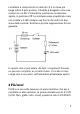
Schema circuitale semplificato di un collegamento in serie La tensione viene suddivisa tra i carichi nel circuito. In questo caso sono presenti due LED e una resistenza. Ogni LED bianco ha bisogno di circa 3 V. Due LED hanno una caduta di tensione di 6 V. E poiché la batteria ha 9 V, rimane una caduta di tensione di 3 V sulla resistenza. In questo caso, la tensione della batteria viene suddivisa in parti uguali tra tre utenze. Il consumo di energia è distribuito esattamente nello stesso modo.
Collegamento in parallelo Il collegamento in parallelo è detto anche “circuito ramificato”. La corrente attraverso la resistenza è divisa in due LED. Metà della corrente passa attraverso un LED, l’altra metà attraverso l’altro LED. Un piccolo test può dimostrarlo: se il cavo tra i due LED viene rimosso, un LED si spegne, ma l’altro si illumina. L’intera corrente poi scorre attraverso i LED stessi.
Collegamento in parallelo con due LED 7 Gruppo ottico Morse Un interruttore a pulsante accende e spegne il LED di segnalazione in questo test. Il risultato è un semplice dispositivo Morse. Il LED di segnalazione funziona ad alta luminosità. Inoltre, è presente un LED con luce continua più debole, che può essere acceso tramite l’interruttore 1.
Info Codice Morse 17
Segnali verdi 8 In questo caso, al posto del LED di segnalazione bianco, viene installato un LED verde. La luce di questo LED può essere vista da distanze ancora maggiori. Ciò permette lo scambio di messaggi con gli amici.
9 Un dispositivo di prova elettrico In questo esperimento viene costruito un dispositivo di prova con il quale si può controllare quali elementi conducono la corrente. La resistenza con 10 kΩ (marrone, nero, arancione) dovrebbe ridurre ulteriormente la corrente attraverso il LED, perché qui non è necessaria molta luminosità. A tale scopo sono disponibili due cavi con puntali di prova. È possibile utilizzarli per toccare qualsiasi oggetto .
20
Test aggiuntivo Il dispositivo di test è adatto anche per il test di componenti elettrici. Le resistenze nel pacchetto conducono la corrente in modo diverso. Un LED conduce in una sola direzione. Inoltre, è possibile verificare se una lampada a incandescenza è ancora funzionante o si è già bruciata. 10 Luce rossa e verde Lo scopo di questo esperimento è quello di confrontare la luminosità dei LED di diversi colori. Al LED verde deve essere collegato in serie un LED rosso.
22
11 Interruttore colore 11 A Con una resistenza di 2,2 kΩ (rosso, rosso, rosso) e due LED si deve realizzare un circuito molto speciale, un interruttore verde-rosso. Ogni volta che si preme il pulsante, il LED rosso si accende, mentre il LED verde si spegne. Con il contatto di commutazione chiuso si tratta in realtà solo di un normale collegamento in parallelo come nella prova 6, ma allora sono stati utilizzati due LED identici, questa volta due LED diversi.
Il backup PTC Tutti gli esperimenti utilizzano un backup che ha effetto quando si verifica un errore. In caso di cortocircuito involontario, un filo potrebbe surriscaldarsi o la batteria potrebbe surriscaldarsi e, nel peggiore dei casi, esplodere. Il fusibile può prevenire questo pericolo. Molti fusibili saltano semplicemente quando si attiva un cortocircuito. Ma questo fusibile speciale è diverso. Si tratta di un fusibile autoreset, noto anche come fusibile PTC.
il fusibile PTC si riscalda e lascia passare solo pochissima corrente, perché la sua resistenza aumenta notevolmente. È da qui che deriva il nome. PTC sta per “coefficiente di temperatura positivo” e significa che la resistenza aumenta quando la temperatura aumenta. Con una tensione di 9 V si raggiunge una temperatura di circa 60 gradi. Se poi si spegne l’alimentazione e si elimina il guasto, il fusibile si raffredda e torna come nuovo.
13 Luminosità regolabile Il potenziometro (potenziometro corto) è una resistenza regolabile con tre collegamenti. Tali componenti sono utilizzati anche come controlli di volume nelle radio. Qui la luminosità di un LED verde dovrebbe però essere regolata. Più si ruota la manopola verso destra, più il LED diventa luminoso. Finora sono state utilizzate diverse resistenze fra 0,47 kΩ e 10 kΩ.
Il potenziometro aperto 27
14 Rosso – Verde – Bianco Il terzo collegamento del potenziometro può essere effettuato anche con un altro cavo. In questo modo è possibile regolare la tensione elettrica nel circuito. Alla barra di scorrimento del potenziometro sono collegati in totale tre LED. I LED rosso e verde hanno una propria resistenza di serie. Il LED bianco è collegato direttamente, ma alla massima luminosità funziona la resistenza di 470 Ω. Ruotando la manopola fino in fondo verso sinistra, tutti i LED si spengono.
Ulteriori esperimenti: colori dello spettro luminoso Un CD può essere utilizzato come uno specchio per visualizzare i tre LED. Cambiando l’angolo, è possibile vedere il LED bianco come strisce in tutti i colori dell’arcobaleno. Lo spettro della luce è visibile perché il CD ha linee strette che portano a interferenze delle onde luminose. Anche le linee dei LED rosso e verde sono leggermente divise, ma contengono solo una piccola parte dello spettro luminoso. Il LED bianco è in realtà un LED blu.
15 Impostazione da verde a rosso In questo esperimento, viene creata una luce a LED con colore regolabile. Si illumina di rosso o verde o in entrambi i colori. Con il potenziometro è possibile regolare la luminosità di entrambi i LED. Se il LED verde si accende con una rotazione in senso antiorario, il LED rosso si accende più lentamente. E se si ruota il potenziometro più a destra, il LED rosso si illumina e quello verde si indebolisce.
possibile regolare tutti i colori e tutte le sfumature nella gamma rosso – giallo – verde.
16 Luce lampeggiante automatica Il LED rosso lampeggiante è un LED speciale con elettronica interna aggiuntiva. Se installato come un normale LED con una resistenza di serie, si accende e si spegne di continuo. Solo a scopo di confronto, il LED rosso con luminosità regolabile deve essere posizionato accanto ad esso.
Il LED lampeggiante Il LED lampeggiante contiene un transistor che funge da interruttore elettronico. Inoltre, sono necessari ulteriori transistor e altri componenti, che insieme formano un circuito complesso e hanno il compito di controllare che vi sia una temporizzazione esatta. Tutto insieme è costruito su un piccolo pezzo di silicio che è installato accanto al cristallo a LED. 17 Indicatori – rosso e verde Ora l’indicatore dovrebbe essere esteso in modo che due LED lampeggino simultaneamente.
Il principio del collegamento in serie 18 Indicatori alternativi Come funziona il cambio di colore già testato nell’esperimento numero11? Un interruttore a pulsante è stato utilizzato per accendere un LED rosso. Questa volta si utilizzerà l’interruttore automatico integrato nel LED lampeggiante, il controller LED.
collegati in parallelo. E poiché il LED verde ha bisogno di più tensione del LED rosso, lo stesso si accende solo durante le pause di lampeggiamento. Inoltre, il LED con il colore rosa è ora utilizzato. Dovrebbe prima essere provato con luminosità regolabile. Se i LED verde e rosa sono commutati, il LED rosa lampeggia e il LED verde mostra una luce uniforme con luminosità regolabile. Questo dimostra che anche un LED rosa ha bisogno di più tensione di un LED rosso.
Struttura del LED rosa Il LED rosa ha una struttura simile a quella del LED bianco. Il cristallo LED emette luce blu. Tuttavia, esso è coperto da un materiale fluorescente che cattura parte della luce blu e la irradia di nuovo come luce rossa. Ecco perché il LED rosa in realtà ha due colori: Rosso e blu. Uno sguardo sopra un CD lo rivela...
19 Lampeggiatore intermittente a quattro LED Ora è prevista la costruzione di un indicatore di direzione intercambiabile a quattro colori. Un LED giallo è in serie con il LED lampeggiante e quindi lampeggia alla stessa frequenza. Parallelamente è presente un collegamento in serie costituito da un LED verde e da un LED rosa. Questi due LED hanno bisogno di più tensione e si accendono sempre quando rosso e giallo sono spenti.
Test supplementare: Nel circuito devono essere testati diversi resistori di serie. Minore è la resistenza, maggiore sarà la luminosità. In questo caso la commutazione funziona ancora con le resistenze più piccole? 20 Sistema di allarme con indicatore lampeggiante Con due LED è possibile realizzare un semplice sistema di allarme. Il LED verde si accende di continuo, quello rosso no, perché il cavo lo cortocircuita. Verde significa: va tutto bene! È possibile legare un filo al cavo e fissarlo alla porta.
21 Un gioco di abilità In questo gioco si deve cercare di premere il pulsante nello stesso istante in cui si accende il LED rosso lampeggiante. Quando si preme il pulsante, il LED verde rimane spento. Quando viene rilasciato, lampeggia allo stesso ritmo del LED rosso lampeggiante.
(marrone, verde, arancione) e quindi lascia fluire solo poca corrente. Questo è importante perché si devono guardare da vicino i LED in questo gioco, ma senza esserne abbagliati. Ora il pulsante deve essere premuto più e più volte e rilasciato solo brevemente quando il LED lampeggiante è spento. Se la tempistica non viene rispettata, il LED verde lampeggia.
Circuito a ponte Un circuito a ponte è costituito da due circuiti in serie e da un componente inserito tra di essi. Sul lato sinistro il collegamento in serie contiene una resistenza e il LED lampeggiante. Sul lato destro sono presenti un resistore e un interruttore. Tra i due si trova un LED che forma il ponte.
Attenzione, non guardare mai direttamente il LED quando è acceso. La luce blu, in particolare, può danneggiare la retina. Poiché l’occhio è meno sensibile alla luce blu, il LED blu appare meno luminoso, ma è comunque particolarmente pericoloso per gli occhi. In questo test, il LED di cambio colore viene azionato con luminosità regolabile. È possibile effettuare un altro tentativo. Il potenziometro è collegato come divisore di tensione, in modo da poter impostare anche tensioni molto basse a partire da 0 V.
Più corta è la lunghezza d’onda della luce, maggiore è la tensione richiesta dal LED.
Modulazione della larghezza d’impulso I singoli LED non solo si accendono e si spengono, ma appaiono anche più chiari o più scuri. A volte la luminosità aumenta in modo uniforme. Si potrebbe supporre che un qualche tipo di potenziometro sia stato integrato al fine di cambiare la corrente. Ma in realtà i LED si accendono e si spengono in rapida successione. Se si sposta l’intera struttura avanti e indietro rapidamente, è possibile vedere tratti di luce di diverse lunghezze.
24 Luce verde intermittente Questa volta il LED verde dovrebbe accendersi in modalità push-pull per il LED di cambio colore. Occorre collegarlo in parallelo. La resistenza idonea è di 1,5 kΩ (marrone, verde, rosso).
LED rosso, il LED verde si spegne. Questo crea un interessante sfarfallio del LED verde. E anche il LED verde a volte mostra continui cambiamenti di luminosità. test supplementare In questo circuito si possono testare molte resistenze diverse fra 470 kΩ e 22 Ω. In questo modo è possibile impostare livelli di luminosità molto diversi. L’obiettivo può essere una maggiore luminosità (resistenza inferiore) o una maggiore durata della batteria (resistenza superiore).
25 Luce lampeggiante e tremolante con sei LED Con un totale di sei LED e due resistenze identiche a partire da 1 kΩ (marrone, nero, rosso), alla fine deve essere costruita una luce LED colorata e varia, in cui tutti i LED lampeggiano o sfarfallano. In realtà, il pacchetto contiene solo due LED con un controller integrato. Ma ci sono alcuni trucchi di circuito con cui altri LED possono anche lampeggiare o sfarfallare.
Ora sono installati sei LED, ma due LED bianchi sono ancora senza funzione. Può essere un compito interessante installarli ulteriormente. Ci sono modi molto diversi per farlo. Gli esperimenti qui presentati sono fonte di ispirazione. Nel complesso, è ancora possibile sviluppare innumerevoli nuovi circuiti con i componenti esistenti.
testata Cari clienti! Questo prodotto è stato fabbricato in conformità alle direttive europee in vigore e reca pertanto il marchio CE. L’uso previsto è specificato nel file e descritto nel manuale allegato. L’utente è l’unico responsabile della conformità alle norme applicabili per qualsiasi altro uso o modifica del prodotto. Per questo motivo si raccomanda di costruire i circuiti esattamente come descritto nelle istruzioni. Il prodotto può essere trasmesso solo insieme alle presenti istruzioni per l’uso.