Linkerkit Base Set für Raspberry Pi
Linker Kit Base Set Raspberry Pi INHALTSVERZEICHNIS 1. Einführung 2. Das Baseboard 3. Die RGB-LED 4.Das Buttonmodul 5. Der Buzzer 6. Der Bewegungssensor 7. Der Lichtsensor 8. Der Hallsensor 9. Die Digitalanzeige 10. Der Temperatursensor 11. Informations- und Rücknahmepflicht 12. Support Veröffentlicht: 09.10.
Linker Kit Base Set Raspberry Pi 1. EINFÜHRUNG Sehr geehrter Kunde, vielen Dank, dass sie sich für unser Produkt entschieden haben. Im folgenden zeigen wir Ihnen, was bei der Inbetriebnahme und der Verwendung zu beachten ist. Sollten Sie während der Verwendung unerwartet auf Probleme stoßen, so können Sie uns selbstverständlich gerne kontaktieren. Das Linker Kit Base Set für den Raspberry Pi macht die Verwendung verschiedener Module und Sensoren sehr einfach.
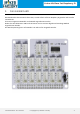
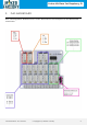
Linker Kit Base Set Raspberry Pi 2. DAS BASEBOARD Das Baseboard ist das Herzstück dieses Sets, es wird einfach auf Ihren Raspberry Pi gesteckt und ist sofort einsatzbereit. Es können insgesamt 18 Module an das Board angeschlossen werden. Neben den zwei bekannten UART und I2C können noch 14 weitere digitale und 4 Analoge Module angeschlossen werden. Die Betriebsspannung kann auf entweder 3.3V oder auf 5V eingestellt werden. Veröffentlicht: 09.10.
Linker Kit Base Set Raspberry Pi 2. DAS BASEBOARD Dem nachfolgendem Bild können Sie einen detaillierten Anschlussplan für das Baseboard entnehmen Veröffentlicht: 09.10.
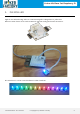
Linker Kit Base Set Raspberry Pi 3. DIE RGB-LED Egal ob zur Beleuchtung oder zur Statusanzeige die LED gehört in jedes Set. Mehrere LEDs lassen sich auch zusammen stecken und gemeinsam ansteuern. Die LED kann in vielen verschiedenen Farben leuchten. Veröffentlicht: 09.10.
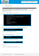
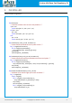
Linker Kit Base Set Raspberry Pi 3. DIE RGB-LED In diesem Beispiel zeigen wir wie Sie die LED leuchten lassen und Ihre Farbe automatisch ändern können. Dies geht mit der Neopixel Bibliothek ganz einfach. Diese müssen wir jedoch zunächst herunterladen, zusätzlich laden wir auch direkt die Beispieldatei herunter. Geben sie folgende Befehle ins Terminal ein: sudo apt-get update sudo apt-get install build-essential python-dev git scons swig git clone https://github.
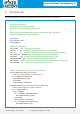
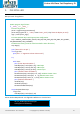
Linker Kit Base Set Raspberry Pi 3. DIE RGB-LED Auf den folgenden 3 Seiten ist der Beispielcode noch einmal in Textform: #!/usr/bin/env python3 # NeoPixel library strandtest example # Author: Tony DiCola (tony@tonydicola.com) # # Direct port of the Arduino NeoPixel library strandtest example. Showcases # various animations on a strip of NeoPixels. import time from neopixel import * import argparse # LED strip configuration: LED_COUNT = 16 # Number of LED pixels.
Linker Kit Base Set Raspberry Pi 3. DIE RGB-LED Beispielcode fortgeführt: def wheel(pos): """Generate rainbow colors across 0-255 positions.""" if pos < 85: return Color(pos * 3, 255 - pos * 3, 0) elif pos < 170: pos -= 85 return Color(255 - pos * 3, 0, pos * 3) else: pos -= 170 return Color(0, pos * 3, 255 - pos * 3) def rainbow(strip, wait_ms=20, iterations=1): """Draw rainbow that fades across all pixels at once.""" for j in range(256*iterations): for i in range(strip.numPixels()): strip.
Linker Kit Base Set Raspberry Pi 3. DIE RGB-LED Beispielcode fortgeführt: # Main program logic follows: if __name__ == '__main__': # Process arguments parser = argparse.ArgumentParser() parser.add_argument('-c', '--clear', action='store_true', help='clear the display on exit') args = parser.parse_args() # Create NeoPixel object with appropriate configuration.
Linker Kit Base Set Raspberry Pi 4. DAS BUTTONMODUL Das Buttonmodul eignet sich hervorragend zum steuern anderer Module und kann für viele verschiedene Aufgaben verwendet werden. Veröffentlicht: 09.10.
Linker Kit Base Set Raspberry Pi 4. DAS BUTTONMODUL In diesem Beispiel kombinieren wir die bereits kennengelernte LED mit dem Buttonmodul. Wir werden diesmal die LED mittels Knopfdruck zum Leuchten bringen. Schließen Sie die LED an Digital-Pin 12 und den Button an Digital-Pin 15 an. Bitte kopieren sie den folgenden Code vollständig und fügen Sie ihn in Ihr Skript ein.
Linker Kit Base Set Raspberry Pi 5. DAS BUZZERMODUL Dieser Buzzer kann an Digitale Ausgänge angeschlossen werden, um einen Ton zu erzeugen. Alternativ kann er an einem Analogen Impulsbreitenmodulationsausgang angeschlossen werden um unterschiedliche Töne und Effekte zu erzeugen Veröffentlicht: 09.10.
Linker Kit Base Set Raspberry Pi 5. DAS BUZZERMODUL In diesem Beispiel nehmen wir das das Buttonmodul und kombinieren es mit dem Buzzermodul, sodass der Buzzer, bei jedem drücken des Knopfes ertönt. Der Buzzer wird in diesem Beispiel an dem Steckplatz mit dem digitalen Port 14 und der Button an den mit dem digitalen Port 15 angeschlossen. Bitte kopieren sie den folgenden Code vollständig und fügen Sie ihn in Ihr Skript ein.
Linker Kit Base Set Raspberry Pi 6. DER BEWEGUNGSSENSOR Dieser Bewegungssensor hat einen Erfassungswinkel von 120° und eine Reichweite von bis zu 6 Metern. Mit diesem Sensor kann man zum Beispiel Lampen bauen, die sich automatisch einschalten wenn man den Raum betritt. Bewegungssensoren werden auch oft in Alarmanlagen eingesetzt. Veröffentlicht: 09.10.
Linker Kit Base Set Raspberry Pi 6. DER BEWEGUNGSSENSOR In diesem Beispiel Kombinieren wir den Bewegungssensor mit dem Buzzer, sodass sobald das Modul eine Bewegung erkennt ein Alarmton ausgegeben wird. Verbinden Sie den Bewegungssensor mit Digital-Pin 14 und den Buzzer mit Digital-Pin 15. Bitte kopieren sie den folgenden Code vollständig und fügen Sie ihn in Ihr Skript ein. Speichern Sie die Datei am Besten in Ihrem Dokumente Ordner unter dem Namen Pir.py import RPi.GPIO as GPIO import time GPIO.
Linker Kit Base Set Raspberry Pi 7. DER LICHTSENSOR Dieser Lichtsensor ist ein vom Licht abhängiger Widerstand (LDR). Der Widerstand des Sensors verringert sich, sobald die Helligkeit in der Umgebung zu nimmt. Mit Hilfe dieses Sensors kann man eine Lampe bauen, die automatisch an geht sobald es dunkel wird. Veröffentlicht: 09.10.
Linker Kit Base Set Raspberry Pi 7. DER LICHTSENSOR In diesem Beispiel kombinieren wir den Lichtsensor mit der LED, um die LED einzuschalten sobald es dunkel wird. Um Dunkelheit zu simulieren können sie den Lichtsensor einfach mit der Hand abdecken. Schließen Sie die LED an Digital-Pin 12 und den Lichtsensor an Analog-Pin 0 an. Bitte kopieren sie den auf den nächsten zwei Seiten folgenden Code vollständig und fügen Sie ihn in Ihr Skript ein.
Linker Kit Base Set Raspberry Pi 7. DER LICHTSENSOR Beispielcode fortgeführt. if __name__ == '__main__': parser = argparse.ArgumentParser() parser.add_argument('-c', '--clear', action='store_true', help='clear the display on exit') args = parser.parse_args() strip = Adafruit_NeoPixel(LED_COUNT, LED_PIN, LED_FREQ_HZ, LED_DMA, LED_INVERT, LED_BRIGHTNESS, LED_CHANNEL) strip.begin() while True: value = readadc(SENSOR) print("Value: " + str(value)) time.sleep(0.
Linker Kit Base Set Raspberry Pi 8. DER HALLSENSOR Mit diesem Hallsensor können Sie Magnetfelder in der Umgebung, mit Hilfe des Hall-Effekts, erfassen. Veröffentlicht: 09.10.
Linker Kit Base Set Raspberry Pi 8. DER HALLSENSOR In diesem Beispiel kombinieren wir den Hallsensor und den Buzzer. Wenn der Sensor ein Magnetfeld erkennt wird der Buzzer ein Signal von sich geben. Verbinden Sie den Hallsensor mit Digital-Pin 14 und den Buzzer mit Digital-Pin 15 Bitte kopieren sie den folgenden Code vollständig und fügen Sie ihn in Ihr Skript ein. Speichern Sie die Datei am Besten in Ihrem Dokumente Ordner unter dem Namen Hall.py import RPi.
Linker Kit Base Set Raspberry Pi 9. DIE DIGITALANZEIGE Mit Hilfe der Digitalanzeige können wir uns die Zeit oder andere Daten anzeigen lassen. Sie wird in vielen industriellen Lösungen wie Aufzügen verwendet! Und wird für Sie in der Zukunft mit Sicherheit von Nutzen sein. Veröffentlicht: 09.10.
Linker Kit Base Set Raspberry Pi 9. DIE DIGITALANZEIGE In diesem Beispiel werden wir die aktuelle Uhrzeit auf der Digitalanzeige anzeigen lassen. Dafür müssen wir zunächst eine zusätzliche Konfigurations-Datei mit dem Namen „tm1637.py“ anlegen. In diese Datei kopieren wir folgenden Code. Der Code ist ziemlich umfangreich, deshalb haben wir ihn auf vier Seiten aufgeteilt. Speichern Sie die Datei am Besten in Ihrem Dokumente Ordner unter dem Namen tm1637.py import sys import os import time import RPi.
Linker Kit Base Set Raspberry Pi 9. DIE DIGITALANZEIGE Code fortgeführt: def Clear(self): b = self.__brightnes; point = self.__doublePoint; self.__brightnes = 0; self.__doublePoint = False; data = [0x7F,0x7F,0x7F,0x7F]; self.Show(data); self.__brightnes = b; # restore saved brightnes self.__doublePoint = point; # end Clear def ShowInt(self, i): s = str(i) self.Clear() for i in range(0,len(s)): self.Show1(i, int(s[i])) def Show( self, data ): for i in range(0,4): self.__currentData[i] = data[i]; self.
Linker Kit Base Set Raspberry Pi 9. DIE DIGITALANZEIGE Code fortgeführt: if( self.__brightnes != brightnes): self.__brightnes = brightnes; self.Show(self.__currentData); # end if # end SetBrightnes def ShowDoublepoint(self, on): # shows or hides the doublepoint if( self.__doublePoint != on): self.__doublePoint = on; self.Show(self.__currentData); # end if # end ShowDoublepoint def writeByte( self, data ): for i in range(0,8): IO.output( self.__Clkpin, LOW) if(data & 0x01): IO.output( self.
Linker Kit Base Set Raspberry Pi 9. DIE DIGITALANZEIGE Code fortgeführt: def start(self): IO.output( self.__Clkpin, HIGH) # send start signal to TM1637 IO.output( self.__Datapin, HIGH) IO.output( self.__Datapin, LOW) IO.output( self.__Clkpin, LOW) # end start def stop(self): IO.output( self.__Clkpin, LOW) IO.output( self.__Datapin, LOW) IO.output( self.__Clkpin, HIGH) IO.output( self.__Datapin, HIGH) # end stop def coding(self, data): if( self.
Linker Kit Base Set Raspberry Pi 9. DIE DIGITALANZEIGE Nun folgt der eigentliche Code um die Uhrzeit auf dem Display anzeigen zulassen. Die Datei muss im selben Verzeichnis wie die Konfigurations-Datei gespeichert werden. Der Display muss an Digital-Pin 4 angeschlossen werden. Bitte kopieren sie den folgenden Code vollständig und fügen Sie ihn in Ihr Skript ein. Speichern Sie die Datei am Besten in Ihrem Dokumente Ordner unter dem Namen Time.py import sys import time import datetime import RPi.
Linker Kit Base Set Raspberry Pi 10. DER TEMPERATURSENSOR Dieser Temperatursensor verwendet einen Thermistor, um die Umgebungstemperatur zu erfassen. Der Widerstand des Thermistors erhöht sich, wenn die Umgebungstemperatur abnimmt. Durch diese Charakteristik wird die Umgebungstemperatur ausgemessen. Veröffentlicht: 09.10.
Linker Kit Base Set Raspberry Pi 10. DER TEMPERATURSENSOR In diesem Beispiel kombinieren wir den Temperatursensor mit der Digitalanzeige um uns die aktuelle Raumtemperatur anzeigen zulassen. Auch diese Datei muss im selben Verzeichnis wie die Konfigurationsdatei der Digitalanzeige gespeichert werden. Die Konfigurationsdatei muss jedoch auch angepasst werden, die angepasste Version finden Sie ab der nächsten Seite.
Linker Kit Base Set Raspberry Pi 10. DER TEMPERATURSENSOR Auf den nächsten drei Seiten finden Sie die angepasste Konfigurationsdatei tm1637.py Speichern Sie die Konfigurationsdatei in dem Ordner /Documents/Temperature unter dem Namen tm1637.py import sys import os import time import RPi.GPIO as IO IO.setwarnings(False) IO.setmode(IO.
Linker Kit Base Set Raspberry Pi 10. DER TEMPERATURSENSOR Konfigurationsdatei tm1637.py fortgeführt. def ShowInt(self, i): s = str(i) self.Clear() for i in range(0,len(s)): self.Show1(i, int(s[i])) def Show( self, data ): for i in range(0,4): self.__currentData[i] = data[i]; self.start(); self.writeByte(ADDR_AUTO); self.stop(); self.start(); self.writeByte(STARTADDR); for i in range(0,4): self.writeByte(data[i]); self.stop(); self.start(); self.writeByte(0x88 + self.__brightnes); self.
Linker Kit Base Set Raspberry Pi 10. DER TEMPERATURSENSOR Konfigurationsdatei tm1637.py fortgeführt. # wait for ACK IO.output( self.__Clkpin, LOW) IO.output( self.__Datapin, HIGH) IO.output( self.__Clkpin, HIGH) IO.setup(self.__Datapin, INPUT) while(IO.input(self.__Datapin)): time.sleep(0.001) if( IO.input(self.__Datapin)): IO.setup(self.__Datapin, OUTPUT) IO.output( self.__Datapin, LOW) IO.setup(self.__Datapin, INPUT) #endif # endwhile IO.setup(self.__Datapin, OUTPUT) # end writeByte def start(self): IO.
Linker Kit Base Set Raspberry Pi 11. INFORMATIONS- UND RÜCKNAHMEPFLICHTEN Symbol auf Elektro- und Elektronikgeräten Diese durchgestrichene Mülltonne bedeutet, dass Elektro - und Elektronikgeräte nicht in den Hausmüll gehören. Sie müssen die Altgeräte an einer Erfassungsstelle abgeben. Vor der Abgabe haben Sie Altbatterien und Altakkumulatoren, die nicht vom Altgerät umschlossen sind, von diesem zu trennen.
Linker Kit Base Set Raspberry Pi 12. SUPPORT Wir sind auch nach dem Kauf für Sie da. Sollten noch Fragen offen bleiben oder Probleme auftauchen stehen wir Ihnen auch per E -Mail, Telefon und Ticket-Supportsystem zur Seite. E-Mail: service@joy-it.net Ticket-System: http://support.joy-it.net Telefon: +49 (0)2845 98469 – 66 (10- 17 Uhr) Für weitere Informationen besuchen Sie unsere Website: www.joy-it.net Veröffentlicht: 09.10.