
User Manual
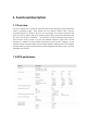
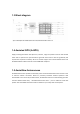
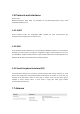
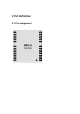
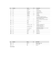
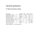
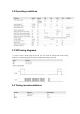
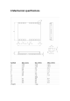
Table Of Contents
- Functional description
- 1.2 GPS performanc
- 1.3 Block diagram
- 1.4 Assisted GPS (A-GPS)
- 1.6.1 UART
- 1.6.2 USB
- 1.6.3 Serial Peripheral Interface (SPI)
- 1.7 Antenna
- 1.8 Power Management
- 1.9 Maximum Performance Mode
- 1.10 Eco Mode
- 1.11 Power Save Mode
- 2 Pin Definition
- 2.1 Pin assignment
- 3 Electrical specifications
- 3.1 Absolute maximum ratings
- 3.2 Operating conditions
- 3.3 SPI timing diagrams
- 3.4 Timing recommendations
- 4 Mechanical specifications

1.6 Protocols and interfaces
Protocol Type
NMEA Input/output, ASCII, 0183, 2.3 (compatible to 3.0) UBX Input/output, binary, u-blox
proprietary RTCM Input, 2.3
1.6.1 UART
GT-U7 modules include one configurable UART interface for serial communication (for
information about configuration see section 1.15).
1.6.2 USB
GT-U7 modules provide a USB version 2.0 FS (Full Speed, 12Mbit/s) interface as an alternative to
the UART. The pull-up resistor on USB_DP is integrated to signal a full-speed device to the host.
The VDDUSB pin supplies the USB interface. u-blox provides a Microsoft® certified USB driver for
Windows XP, Windows Vista and Windows 7 operating systems.
1.6.3 Serial Peripheral Interface (SPI)
The SPI interface allows for the connection of external devices with a serial interface, e.g. serial
flash to save configuration and AssistNow Offline A-GPS data or to interface to a host CPU. The
interface can be operated in master or slave mode. In master mode, one chip select signal is
available to select external slaves. In slave mode a single chip select signal enables
communication with the host.
1.7 Antenna