
User Manual

ROBOT . HEAD to TOE
Product User’s Manual – HAT-MDD10
4
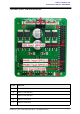
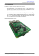
**PWM2 (GPIO13)
PWM input for motor 2 speed control
5
DIR2 (GPIO24)
Direction control for motor 2.
**Note that it is not for RC PWM operation
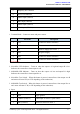
The truth table for the control logic is as follow:
Pin PWM
Pin DIR
Output A
Output B
Low
X (Don’t care)
Low
Low
High
Low
High
Low
High
High
Low
High
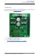
7. Power LED Indicator – Power LED. Should be on when the board is powered on.
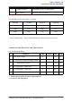
4. PRODUCT SPECIFICATION AND LIMITATIONS
Absolute Maximum Rating
No.
Parameters
Min
Typical
Max
Unit
1
Power Input Voltage
6
-
24
V
2
I
MAX
(Maximum Continuous Motor Current)
-
-
10
A
3
I
PEAK
– (Peak Motor Current) *
-
-
30
A
4
V
IOH
(Logic Input – High Level)
3
-
5.5
V
5
V
IOL
(Logic Input – Low Level)
0
0
0.5
V
6
Maximum PWM Frequency **
-
-
20
KHz
* Must not exceed 10 seconds.
** Actual output frequency is same as input frequency.
*** Tested in room temperature.
Created by Cytron Technologies Sdn. Bhd. – All Rights Reserved 7