Router MODEL 3620 MODEL 3620A Equipped with electric brake INSTRUCTION MANUAL DOUBLE I SPECIFICATIONS Collet chuck capacity 1/4" I Main body stroke 3 5 m m (1-3/8"1 I No I ';k"p"dyed Overall length 24,000 21 1 m m 18-5/16") I A1'ION N e t weight 2.4 k g 15.
IMPORTANT SAFETY INSTRUCTIONS (For All Tools) WARNING: WHEN USING ELECTRIC TOOLS, BASIC SAFETY PRECAUTIONS SHOULD ALWAYS BE FOLLOWED TO REDUCE THE RISK OF FIRE, ELECTRIC SHOCK, AND PERSONAL INJURY, INCLUDING THE FOLLOWING: READ ALL INSTRUCTIONS. 1. KEEP WORK AREA CLEAN. Cluttered areas and benches invite injuries. 2. CONSIDER WORK AREA ENVIRONMENT. Don't use power tools in damp or wet locations. Keep work area well lit. Don't expose power tools t o rain.
14. REMOVE ADJUSTING KEYS AND WRENCHES. Form habit of checking t o see that keys and adjusting wrenches are removed from tool before turning it on. 15. AVOID UNINTENTIONAL STARTING. Don't carry plugged-in tool w i t h finger on switch. Be sure switch is OFF when plugging in. 16. OUTDOOR USE EXTENSION CORDS. When tool is used outdoors, use only extension cords intended for use outdoors and so marked. 17. STAY ALERT. Watch what you are doing, use common sense. Don't operate tool when you are tired. 18.
ADDITIONAL SAFETY RULES 1. Handle the bits very carefully. 2. Check the bit carefully for cracks or damage before operation. Replace cracked or damaged bit immediately. 3. Avoid cutting nails. Inspect for and remove all nails from the workpiece before operation. 4. Hold the tool firmly w i t h both hands. 5. Keep hands away from rotating parts. 6. Make sure the bit is not contacting the workpiece before the switch is turned on. 7. Before using the tool on an actual workpiece, let it run for a while.
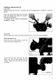
Installing or removing router bit CAUTION : Always be sure that the tool i s switched off and unplugged before installing or removing the bit. Insert the bit all the way into the collet cone and tighten the collet nut securely with the two wrenches. To remove the bit, follow the installation procedure in reverse. Tighten t CAUTION : Do not tighten the collet nut without inserting a bit, or the collet cone will break. Adjusting depth of cut Place the tool on a flat surface.
Next, lower the stopper pole until it makes contact with the adjusting hex bolt. Align the depth pointer with the "0" graduation. Raise the stopper pole until the desired depth of cut i s obtained. The depth of cut is indicated on the scale (1 mm or 1/16" per graduation) by the depth pointer. Then tighten the screw to secure the stopper pole.
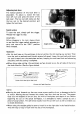
Adjusting lock lever The locked position of the lock lever is adjustable. To adjust it, loosen the lock lever 3/4 turn and press the center of the lock lever. The hex nut will come out. Set the hex nut to the desired position and tighen the lock lever. Switch action To start the tool, simply pull the trigger. Release the trigger to stop. CAUTION: Before plugging in the tool, always check to see that the trigger switch actuates properly and returns to the "OFF" position when released.
Straight guide (optional accessory) The straight guide i s effectively used for straight cuts when chamfering or grooving. To install the straight guide, insert the guide bars into the holes in the tool base. Adjust the distance between the bit and the straight guide. At the desired distance, tighten the wing bolts to secure the straight guide in place. 1 J When cutting, move the tool with the straight guide flush with the side of the workpiece.
Templet guide (optional accessory) The templet guide provides a sleeve through which the bit passes, allowing use of the router with templet patterns. To install the templet guide, loosen the screws on the tool base, insert the templet guide and then tighten the screws. Screw 1 Base plate I - Templet guide Secure the templet to the workpiece. Place the tool on the templet and move the tool with the templet guide sliding along the side of the templet.
ACCESSORIES CAUTION : These accessories or attachments are recommended for use with your Makita tool specified in this manual. The use of any bther accessories or attachments might present a risk of injury t o persons. The accessories or attachments should be used only in the proper and intended manner.
Bits STRAIGHT - Single Flute HIGH SPEED STEEL I I PARTNO. A B C D E 7332326A 118 5/16 i-iia 114 1.518 PART NO. A B C D E 733003-2A 733003-4A 733003.8~ 3/16 1I 4 5/16 7/16 314 1 1.318 1-3/16 1-1/ a 114 1I 4 114 2 2-118 2-3/16 1 I ~ ~ ~~ HINGE MORTISING CARBIDE TIPPED PART NO. A 8 C D E 733006-9A 112 112 1-1/16 1I 4 1-13/16 HIGH SPEED STEEL PART NO. A B C D E 733235-0A 1/2 112 314 114 1-15/16 VEINING -Single Flute i D k SOLID CARBIDE PART NO.
ROUND NOSE %ICARBIDE TIPPED PART NO. 733008-2A 7330084A 733008-6A 733008-8A 733009-0A 1-1I4 1-114 1-114 1-114 1-1/4 15/32 9116 11/16 11/16 13/16 318 112 518 3/4 1-718 1I 4 114 1/4 2-3116 2-114 2-3/8 CORE BOX =/ HIGH SPEED STEEL PART NO. 733238-2A A B C D E 1I4 114 1-3/16 114 1-112 ~~ VEE GROOVING CARBIDE TIPPED PART NO. A B C D E E 733009-2A 733009-4A 318 518 112 314 1-3/16 15116 114 1/4 2 9 0" 90" 2 14" DOVETAIL CARBIDE TIPPED PART NO.
PANEL PILOT HIGH SPEED STEEL C~~~~~ ROUNDING PART NO. A B C D E 733236-0A 114 3/4 1 1/4 2-7/16 CARBIDE TIPPED - Ball Bearing Pilot 733120-0A 733120-2A 733120-4A 733120-6A 733120-EA 7/8 1.118 1-114 1-1/2 112 1/2 112 112 112 3/8 1/2 1-1/4 1-1/4 1.114 1-1/4 1-114 5/8 314 114 114 1/4 1/4 1/4 1-15/16 2-1/16 2-118 2-1/4 3/16 114 5/16 318 112 REPLACEMENT BEARING - NO. 733132-4A HIGH SPEED STEEL -Solid Pilot PARTNO.
45" CHAMFERING CARBIDE TIPPED - Ball Bearins Pilot PARTNO. Ai Az B C D E 733124-4A 1-3/16 1/2 112 1-1/4 114 2-114 REPLACEMENT BEARING -NO, 733132-4A RABBETING -4DC CARBIDE TIPPED - Ball Bearing Pilot PARTNO. Ai Az B C D E 733124-2A 1-1/4 112 1/2 1-7/16 1/4 2-1/4 REPLACEMENT BEARING - NO, 733132-4A ROMAN OGEE idCARBIDE TIPPED - Ball Bearing Pilot ~ PARTNO. Ai A2 B C D E R 733123-2A 733123.4~ 1 1-318 318 318 15/32 21/32 1.114 1.
7" BEVEL TRIMMER - Self-Piloting SOLID CARBIDE PART NO. A B C D E 733128-2A 3/16 114 1-1/16 1/4 1-9/16 PART NO. A 8 C D E 733128-8A 733128-9A 7331 29-OA 318 1I2 1I2 1 1/ 2 1 1-1/4 1-1/4 1-114 1I 4 114 114 2-1/16 2-1/16 2 FLUTE FLUSH TRIMMER CARBIDE TIPPED 2.518 3/8" REPLACEMENT BEARING - NO. 733132-2A 112" REPLACEMENT BEARING -NO. 7331324A COMBINATION FLUSH122" BEVEL TRIMMER -I+ CARBIDE TIPPED I PARTNO.
3 FLUTE 22' BEVEL TRIMMER ASSEMBLY -Self-Piloting -I+ SOLID CARBIDE CUTTER PARTNO. A, A2 B C D E 733129-4A 718 518 318 1.114 114 2-318 REPLACEMENT BEARING - NO. 733132-6A ~ 3 F L U T E FLUSH REPLACEMENTCUTTER CA-I SOLID CARBIDE I PARTNO. A 6 D 733129-6A 518 318 114 1 I FOR FLUSH TRIMMER ASSEMBLY NO. 733129-2A 3 FLUTE 22' BEVEL REPLACEMENT CUTTER SOLID CARBIDE PART NO. A 6 D 733129-8A 718 318 114 FOR BEVEL TRIMMER ASSEMBLY NO.
BALL BEARING PILOT I PARTNO. D1 D? 733132-2A 733132-4A 733132-6A 3/8 O.D. l i 2 O.D. l / 8 I.D. 3/16 I.D. 1/4 1.D 5/8 O.D.
Feb--20-'92 US ROUTER Model 3620 Model 3620A Note: The switch, noise suppressor and other part configurations may differ from country to country.
Feb-20-'92 MODEL 3620, 3620A AtD M \;' DESCRIPTION "0" US DESCRIPTION MACHINE MACHINE ~ ~ 1 1 2 3 1 1 1 1 1 1 4 5 6 7 8 9 10 11 12 13 14 15 16 17 18 19 20 21 22 23 24 25 26 Screw M5x20 Flat Washer 5 pressure Plate Hex Nut M 8 stopper Pole Depth Poinfer Housing Set IWith Item 151 1 1 Cord Cord Guard 1 2 1 Strain Relief 2 2 1 1 1 1 1 1 1 1 1 1 1 1 - Pan Head Screw M4x18 (With Washerl Switch Carbon Brush Brush Holder Housing Set (With Item 71 Flat Washer 8 Lever 45 Retaining Ring R -
P MAKITA LIMITED ONE YEAR WARRANTY Warranty Policy Every Makita tool is thoroughly inspected and tested before leaving the factory. It is warranted to be free of defects from workmanship and materials for the period of ONE YEAR from the date of original purchase. Should any trouble develop during this one-year period, return the COMPLETE tool, freight prepaid, to one of Makita’s Factory or Authorized Service Centers.